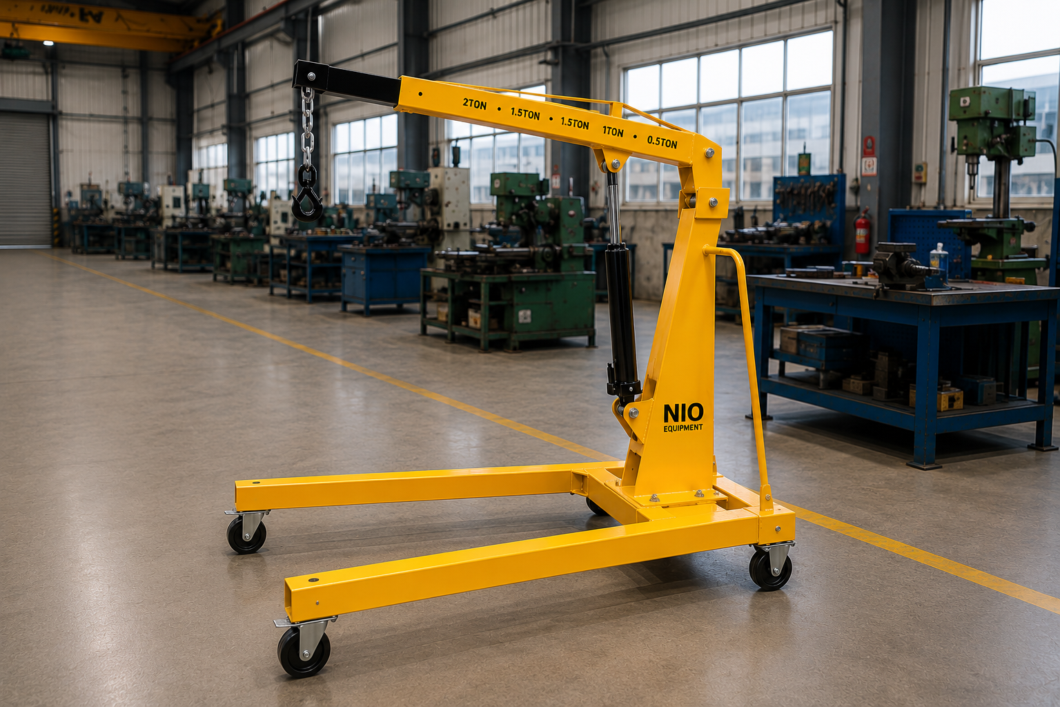
Nio Equipment Wall Mounted Jib Crane provides localized lifting and precise load positioning around machines, assembly stations, maintenance bays, and production lines. Its wall-supported arrangement preserves valuable floor area, while the fabricated steel jib and rigid mounting brackets provide dependable industrial service. The crane can be configured for different load capacities, boom lengths, hoist types, slewing arrangements, mounting conditions, and finishes to match application and site requirements.
Specifications
| Load Capacity | 125 kg to 5,000 kg |
| Boom Reach | 2 m to 8 m |
| Lift Height | 3 m to 12 m |
| Rotation Angle | Up to 180° |
| Hoist Type | Manual chain hoist, electric chain hoist, wire rope hoist |
| Hoist Speed | 4 m/min to 8 m/min |
| Power Supply | 415 V, 3-phase, 50 Hz for electric operation |
| Slewing Operation | Manual push-pull or electric motorized |
| Mounting Arrangement | Fabricated steel wall or structural column brackets |
| Jib Construction | Rolled steel I-beam or fabricated box-section boom |
Key Features
- Wall-supported design preserves valuable floor space
- Smooth trolley travel enables controlled load movement
- Rigid bracket construction supports stable operation
- Compact geometry serves individual work areas
- Heavy-duty fabricated steel load-bearing structure
- Accessible components simplify routine maintenance
- Localized coverage streamlines workstation handling
Optional Configurations
- Load Capacity – Rated capacity can be selected to match the lifted component, hoist, trolley, attachment, and required industrial duty.
- Boom Length – Jib length and working radius can be tailored around machinery layouts, aisle clearances, and material pickup points.
- Hoist Selection – Choose manual chain, electric chain, or wire rope hoisting to suit load frequency, travel height, and positioning requirements.
- Slewing Operation – Manual push-pull or motorized slewing can be specified according to load weight, operating frequency, and handling precision.
- Mounting Arrangement – Wall and structural column brackets can be engineered around the available supporting structure and required load reactions.
- Protective Finish – Paint system, corrosion protection, and industrial color can be selected for indoor, outdoor, or application-specific operating environments.
Safety Features
- Overload Protection
- Emergency Stop Control
- Hoist Limit Switches
- Fail-Safe Hoist Brake
- Mechanical Slewing Stops
- Rated Load Marking
Certifications & Standards
Use Cases
Product Resources
What Is a Wall Mounted Jib Crane?
A Wall Mounted Jib Crane is a material handling device fixed to a building wall or structural column, used for lifting and positioning loads within a confined workstation. Designed to save floor space, it supports localized lifting tasks such as machine servicing and component assembly in industrial environments.
Working Principle of Wall Mounted Jib Crane
The Wall Mounted Jib Crane operates by pivoting a horizontal boom mounted rigidly to a vertical wall bracket or column. Loads are lifted vertically via hoists attached to the boom. Horizontal slewing movement occurs by manually or electrically rotating the boom arm, enabling load positioning over a fixed radius. The structure transfers load forces directly into supporting walls or columns, avoiding floor obstructions.
Step-by-Step Operation
- Attach load to the selected hoist mechanism securely.
- Lift the load vertically using manual or powered hoist.
- Slew the jib arm horizontally within the rotation range to move the load.
- Traverse the trolley along the boom if applicable for load positioning.
- Lower the load precisely at the destination point.
- Detach the load from the hoist.
- Return hoist and jib to resting position for next use.
Key Components
Safety Features - Detailed
- Overload protection prevents lifting beyond rated capacity
- Emergency stop control immediately halts operation
- Hoist limit switches prevent over-travel
- Fail-safe hoist brake maintains load on failure
- Mechanical slewing stops prevent over-rotation
- Clear rated load marking ensures correct use
- Stable wall mounting avoids structural failure
- Smooth trolley travel reduces load swing
- Regular safety inspections required for compliance
- Operator training mitigates misuse and accidents
- Control devices allow safe and precise handling
- Installation per structural guidelines ensures safety
- Protective finishes prevent corrosion-induced hazards
- Safe access for maintenance prevents injury
Selection Factors
- Required load capacity
- Boom reach and length
- Lift height and travel distance
- Type of hoist mechanism
- Slewing mode manual or motorized
- Wall or column structural integrity
- Installation space availability
- Frequency of operation
- Load frequency and weight
- Environmental conditions
- Safety and compliance requirements
- Maintenance accessibility
- Application-specific attachments
- Protective finish requirements
Installation Requirements
- Adequate structural wall or column strength
- Level mounting surface or bracket
- Electrical power supply for hoist motors
- Clearance for full slewing radius
- Proper anchor bolt installation
- Access for installation and maintenance
- Load testing and commissioning protocols
- Operator training for safe use
- Correct alignment of boom and hoist
- Provision for protective coatings in corrosive areas
Maintenance Requirements
- Inspect structural welds and brackets regularly
- Lubricate slewing bearings and trolley wheels
- Verify condition of hoist chains and ropes
- Check operation of limit switches
- Test fail-safe hoist brake function
- Inspect electrical connections and controls
- Confirm rated load markings are legible
- Tighten structural bolts periodically
- Clean trolley and hoist assemblies
- Examine for corrosion or paint damage
- Monitor hoist speed and operation smoothness
- Check emergency stop function
- Inspect mechanical slewing stops
- Review safety features before operation
Advantages of Wall Mounted Jib Crane
- Preserves valuable floor space
- Enables precise load positioning
- Reduces manual material handling
- Supports localized workstation coverage
- Compact footprint fits tight areas
- Rigid steel construction for stability
- Flexible hoist and trolley selection
- Custom boom lengths for layout fit
- Manual or motorized slewing options
- Minimizes load damage risks
- Integrates with existing walls or columns
- Smooth trolley travel for controlled moves
- Accessible for routine maintenance
- Improves productivity at workstations
- Facilitates machine maintenance and assembly
Limitations of Wall Mounted Jib Crane
- Requires strong wall or column support
- Limited rotation angle compared to gantry cranes
- Fixed installation location
- Not suitable for large-area load coverage
- Capacity limited by mounting structure strength
- Boom length restricted by wall structure
- Manual slewing requires operator effort
- Requires electrical supply for motorized options
- Not ideal for outdoor corrosive environments without protection
- Limited vertical lift height compared to floor cranes
Common Alternatives to Wall Mounted Jib Crane
Industry Applications
- Automotive Component Lifting
- Tooling Changeovers
- Precision Fixture Positioning
- Assembly Line Material Transfer
- Motor and Gearbox Installation
- Production Support Material Handling
- Supports organized material flow
- Improves workstation efficiency
- Reduces manual handling risks
- Enables precise load positioning
- Minimizes production interruptions
- Reclaims valuable floor space
- Machined Component Handling
- Fabricated Part Transfer
- Tool Room Material Movement
- Work-in-Progress Lifting
- Assembly Station Equipment Handling
- Workshop Maintenance Support
- Streamlines material flow
- Reduces handling interruptions
- Improves coordination between areas
- Enhances workshop space usage
- Facilitates controlled load movement
- Simplifies routine maintenance
- Storage Level Load Transfer
- Mezzanine Material Handling
- Receiving Area Component Movement
- Dispatch Zone Load Positioning
- Order Preparation Material Transfer
- Warehouse Stock Repositioning
- Supports vertical inventory movement
- Reduces manual handling effort
- Improves stock organization
- Enhances space utilization
- Enables smooth material transitions
- Reduces handling interruptions
- Carton Transfer Between Lines
- Packaging Material Handling
- Production Support Material Movement
- Finished Goods Loading
- Dispatch Area Material Transfer
- Storage Area Lifting
- Facilitates smooth material flow
- Improves load handling speed
- Enhances coordination between levels
- Minimizes manual transfer effort
- Supports efficient space use
- Reduces material damage risk
- Packaged Product Lifting
- Secondary Packaging Handling
- Carton Transfer Operations
- Production Support Material Handling
- Container Positioning
- Storage Area Material Movement
- Enables controlled material movement
- Supports organized workflow
- Reduces manual handling risks
- Improves load positioning accuracy
- Maintains operational area order
- Facilitates efficient level transitions
- Receiving Area Load Positioning
- Storage Level Transfer
- Dispatch Zone Material Handling
- Operational Floor Load Movement
- Staging Area Transfer
- Package Loading and Unloading
- Maintains continuity of goods flow
- Enhances coordination between areas
- Reduces manual load handling
- Supports efficient vertical transfers
- Improves operational space usage
- Minimizes handling interruptions
- Raw Material Handling
- Component Assembly Transfer
- Work-in-Progress Movement
- Finished Goods Handling
- Production Support Load Transfer
- Machine Maintenance Support
- Enables organized material flow
- Supports production line continuity
- Reduces handling cycle times
- Improves workstation productivity
- Minimizes load damage
- Reclaims floor space
Applications
Industries Served
Customization Options
How Wall Mounted Jib Crane Compares to Alternatives
| Alternative | Key Difference |
|---|---|
| Pillar Mounted Jib Crane | Pillar mounted jib cranes use a freestanding column for support offering flexible positioning without reliance on wall structure. |
| Floor Crane | Floor cranes occupy floor space and provide mobility for moving loads across larger areas compared to fixed wall-mounted jib cranes. |
| Mobile Floor Crane | Mobile floor cranes combine portability and lifting capability for variable job sites where fixed-wall installation is not feasible. |
| Hydraulic Floor Crane | Hydraulic floor cranes incorporate powered lifts suited for heavier loads and greater vertical travel but require floor space and mobility. |
| Gantry Crane | Gantry cranes span large work areas for overhead lifting requiring floor clearance and wider spatial coverage compared to localized wall-mounted cranes. |
| Electric Hoist Systems | Electric hoists provide powered lifting often integrated into overhead supports but lack the full structural support and locality of jib cranes. |
| Chain Block Hoist | Manual chain block hoists offer simple lifting with minimal installation, but without the dedicated structural support and precise positioning of jib cranes. |
| Industrial Forklift | Industrial forklifts are mobile load carriers suited for palletized goods and bulk transport rather than fixed, precise lifting operations. |
✓ When to Choose Wall Mounted Jib Crane
- When floor space is limited or must remain clear for operational safety and efficiency.
- When lifting requirements involve localized workstation servicing, such as machine maintenance or tooling changeovers.
- When the load weight is within 125 kg to 5,000 kg and requires controlled slewing up to 180 degrees.
- When installation can secure a strong wall or structural column capable of supporting the crane’s rated capacity.
- When repetitive lifting tasks necessitate reduced manual handling and improved workstation throughput.
- When customization of boom length, hoist type, and slewing operation are needed to integrate with existing layout and workflow.
⚠ When Not to Choose Wall Mounted Jib Crane
- When large-area load coverage or heavy load transfer over extensive floor space is required, consider gantry or floor cranes.
- When the supporting wall or column lacks sufficient strength or structural integrity to mount the crane safely.
- When lifting operations demand vertical travel beyond 12 meters or very high speed hoisting, hydraulic or floor cranes may be better.
- When frequent relocation or flexible workspace setups are needed, mobile floor cranes or forklifts provide greater mobility.
- When the work environment is highly corrosive or outdoors without available protective finishes, alternative protected cranes or covers are preferable.
- When manual slewing would impose excessive operator fatigue or imprecise handling, electric slewing or motorized systems should be evaluated.
Ideal Applications for Wall Mounted Jib Crane
Who Uses This Product?
Request a Custom Quote - What We Need to Know
- What is the maximum load capacity required for the wall mounted jib crane?
- What is the required boom reach or working radius in meters?
- What is the necessary lift height or vertical travel distance for your application?
- Which type of hoist do you prefer: manual chain hoist, electric chain hoist, or wire rope hoist?
- What is the expected operating frequency or number of lifting cycles per day?
- What type of structural wall or column support is available for mounting the crane?
- Is slewing operation preferred as manual push-pull or electric motorized?
- What are the dimensions and approximate weight of the loads to be lifted?
- What is the intended application environment: indoor, outdoor, or corrosive?
- Do you require any specific protective finish or paint system for the crane?
Upgrade Options
Frequently Asked Questions
Why Choose NIO Equipment for Wall Mounted Jib Crane
Trusted by manufacturers, warehouses and industrial facilities across India for quality, reliability and after-sales excellence.
- ✓Application-specific crane engineering
- ✓In-house structural manufacturing capability
- ✓Site-responsive mounting design
- ✓Integrated hoist control options
- ✓Industrial installation planning support
- ✓Dedicated after-sales service coordination
About This Product
The Wall Mounted Jib Crane from Nio Equipment is a fixed, wall-supported lifting system for localized material handling within production, maintenance, assembly, and storage areas. By transferring operating loads into a suitable building wall or structural column, it provides vertical lifting and horizontal positioning without requiring a freestanding mast on the factory floor. This arrangement is particularly relevant where aisle access, machine clearance, or usable workstation space must be preserved.
Localized Load Movement
The crane combines hoist lifting, trolley travel, and jib slewing to move a load within a defined working radius. The hoist raises or lowers the load, the trolley positions it along the boom where applicable, and the boom rotates through an angle of up to 180 degrees. These coordinated movements support controlled transfers between a pickup point, machine, fixture, assembly position, maintenance area, or nearby storage location.
Workstation Integration
Compact geometry makes the Wall Mounted Jib Crane suitable for repetitive lifting at individual workstations rather than wide-area transport across an entire facility. Typical workflows include loading machine components, replacing motors, positioning welding fixtures, changing tooling, and transferring work-in-progress between nearby process points. The fixed coverage zone helps organize material movement around a known load path while reducing dependence on forklifts or larger cranes for routine localized tasks.
Operating Principle
A rolled steel I-beam or fabricated box-section boom pivots from rigid brackets attached to an engineered wall or structural column. Loads are suspended from a manual chain hoist, electric chain hoist, or wire rope hoist selected for the required capacity, lift height, frequency, and positioning duty. Slewing may be performed by manual push-pull movement or an electric motorized arrangement, depending on load weight and operating requirements.
Application Range
Available project parameters cover rated capacities from 125 kg to 5,000 kg, boom reaches from 2 m to 8 m, and lift heights from 3 m to 12 m. Hoist speeds for powered configurations range from 4 m/min to 8 m/min, with the final selection coordinated with the load, workflow, and supporting structure. Standard applications are primarily in indoor industrial environments, while outdoor or corrosive locations require an appropriate protective finish and engineering review.
Applications
Machine Component Loading
At machine tools and production equipment, the crane can pick up a machined component from a cart, staging position, or nearby fixture and place it into the working area. Vertical hoisting and trolley movement allow the operator to approach the loading point with greater control than manual handling. Boom length and mounting position should be planned around machine doors, guards, controls, and maintenance access.
Maintenance Bay Handling
Maintenance teams can use the crane to remove and reinstall motors, pumps, gearboxes, and other serviceable assemblies within a defined bay. The load can be raised clear of its mounting location, slewed toward a service area, and lowered onto a suitable support. This workflow reduces the need to bring a mobile floor crane or forklift into a congested machine-side area for every maintenance task.
Assembly Station Lifting
In equipment assembly, the crane supports the controlled placement of components, subassemblies, fixtures, and production materials at the build station. An electric chain hoist may be selected for repetitive powered lifting, while manual hoisting may suit less frequent operations and lighter duty. The selected hook, attachment, and rigging must match the component geometry and maintain load stability during positioning.
Tooling And Fixture Changes
Tool rooms, fabrication shops, and automotive production areas frequently require dies, tooling fixtures, or welding fixtures to be moved between storage stands and operating positions. A workstation jib crane keeps this movement within a dedicated radius and enables controlled lowering onto locating points. Smooth trolley travel and limited slewing help operators align tooling while avoiding uncontrolled manual carrying.
Production Material Transfer
The crane can support raw material, work-in-progress, and finished component movement between adjacent stages of a production line. It is most effective where pickup and delivery positions fall within the boom radius and where a fixed, repeatable handling path is beneficial. For transfers extending across large production areas, a gantry crane, bridge crane, forklift, or other mobile system may be more appropriate.
Fabrication Shop Support
In metal fabrication areas, the Wall Mounted Jib Crane can position fabricated parts, machined items, welding assemblies, and fixtures at benches or process equipment. The wall-supported arrangement leaves the floor available for worktables, carts, and operator movement. A suitable lifting attachment may be required where the load cannot be handled safely with conventional slings and hooks.
Warehouse Positioning Tasks
Within receiving, storage, mezzanine, staging, or dispatch zones, the crane can reposition packaged goods, crates, containers, order bins, and selected inventory components. It may also assist with transfers between nearby storage elevations when the lift height and boom coverage suit the layout. Palletized loads require compatible handling attachments, adequate headroom, and confirmation that their weight and load center remain within the engineered rating.
Packaging Line Handling
FMCG and pharmaceutical support areas may use the crane for cartons, containers, secondary packaging, production supplies, and packaged products where controlled localized lifting is required. The system can bridge short gaps between a staging area, packaging line, storage point, or dispatch position. Protective finish, lifting attachment, and operating practices should be selected for the conditions of the specific production environment.
Benefits
Clearer Factory Floors
Mounting the jib to a suitable wall or structural column removes the need for a floor-standing crane mast within the operating zone. This can preserve aisle space, reduce interference around machinery, and leave more usable floor area for production equipment or material staging. The benefit depends on the availability of a structure capable of accepting the crane reactions.
Reduced Manual Handling
Hoist-assisted lifting replaces the direct raising and carrying of heavy components during assembly, maintenance, and production support activities. The operator can control vertical movement and guide the suspended load within a defined radius instead of relying on physical lifting effort. This supports safer handling practices when combined with correct rigging, training, and operating procedures.
Controlled Load Positioning
The combination of vertical hoisting, boom rotation, and trolley travel allows a load to be positioned at machines, fixtures, benches, and maintenance points. Smooth trolley movement helps reduce abrupt transfers that can cause load swing or component contact. Suitable hoist and slewing selections can further align the crane with the precision and frequency required by the application.
Shorter Handling Cycles
A crane permanently located at the workstation can be available whenever a recurring lift is required, reducing delays associated with obtaining shared mobile handling equipment. This can support production continuity during component loading, tooling changes, and planned maintenance. Actual cycle improvement depends on layout, operator practices, rigging methods, and upstream material availability.
Configuration Around Workflows
Capacity, boom length, hoist type, slewing method, mounting arrangement, and protective finish can be configured around the intended load path. This enables the crane to fit machinery layouts and pickup points rather than forcing the workflow around a generic lifting system. All configuration choices remain subject to application and structural engineering evaluation.
Lower Handling Damage Risk
Controlled lifting and guided positioning reduce the need to drag, carry, or repeatedly set down industrial components. This can help protect machined surfaces, tooling, packaged goods, and work-in-progress from handling impacts. Correct rigging and stable load control remain essential because the crane itself cannot compensate for an unsuitable attachment or an unbalanced load.
Technical Highlights
Rated Working Range
The Wall Mounted Jib Crane is available with load capacities from 125 kg to 5,000 kg, boom reach from 2 m to 8 m, and lift height from 3 m to 12 m. Rotation is available up to 180 degrees for localized coverage along the supporting wall or column. Final values are selected together because increased reach, load rating, mounting reactions, and support strength are interdependent.
Fabricated Load Structure
The load-bearing assembly uses heavy-duty fabricated steel construction with a rolled steel I-beam or fabricated box-section boom. Rigid wall or structural column brackets support the pivot arrangement and transmit vertical and overturning forces into the mounting structure. Structural bolts, fasteners, welds, pivot bearings, and bracket alignment are therefore central to safe and smooth operation.
Hoist And Trolley Options
The boom may be equipped with a manual chain hoist, electric chain hoist, or wire rope hoist according to load frequency, lifting height, positioning needs, and industrial duty. Powered hoist speeds are available from 4 m/min to 8 m/min. A trolley assembly provides movement along the boom where required, extending positioning capability between the pivot and outer working radius.
Manual Or Powered Slewing
Manual push-pull slewing can suit lighter loads, moderate operating frequency, and applications where the operator can safely guide the load. Electric motorized slewing may be configured for heavier loads, frequent movement, or reduced operator effort. The selected arrangement must account for load inertia, desired control, clearances, and the established rotation limits.
Electrical And Control System
Electric operation is based on a 415 V, three-phase, 50 Hz industrial power supply. Depending on the selected powered functions, the system includes the necessary power connection, control pendant, electrical controls, and emergency stop provision. Cable routing and control placement should avoid snagging, crushing, and interference throughout trolley and boom movement.
Integrated Safety Functions
Supported safety provisions include overload protection, hoist limit switches, a fail-safe hoist brake, emergency stop control, mechanical slewing stops, and rated load marking. Limit switches restrict hoist over-travel, while the brake is intended to hold the suspended load if hoist power or motion is interrupted. Mechanical stops establish the permitted slewing range and help prevent the boom from entering an unintended area.
Application Based Finishes
Protective finish and industrial color can be selected for indoor, outdoor, or application-specific environments. Standard use is primarily intended for controlled indoor industrial conditions, so corrosive atmospheres or exposed outdoor sites require additional consideration. Coating selection should reflect moisture, chemicals, cleaning practices, abrasion, and maintenance accessibility.
Industries Served
General Manufacturing
Manufacturing facilities use localized lifting for raw materials, component assemblies, work-in-progress, finished items, and machine maintenance equipment. A wall-mounted crane can connect nearby staging and process points without placing a freestanding column in the production area. Capacity, reach, and hoist type can be selected around the recurring load and production sequence.
Automotive Production
Automotive workstations handle engine components, gearbox assemblies, motors, tooling fixtures, and production parts that require controlled placement. The crane can support assembly line transfer, tooling changeovers, fixture positioning, and equipment installation within a defined station. Motorized slewing or electric hoisting may be considered where load weight and handling frequency would make manual movement inefficient.
Engineering Workshops
Engineering and machine tool workshops routinely move machined components, fabricated parts, assembly fixtures, tooling, and maintenance equipment. Installing the crane beside a machine, inspection station, or assembly bench provides a dedicated handling resource for repetitive tasks. Custom boom length and bracket design help integrate the system with existing machines and constrained workshop layouts.
Metal Fabrication
Fabrication operations require parts and welding fixtures to be transferred between stands, benches, machines, and assembly positions. The rigid steel jib structure supports controlled movement while preserving floor area for worktables and fabrication carts. Load attachments should be selected carefully for irregular, long, or offset fabricated components.
Warehousing And Logistics
Warehouses and logistics facilities can apply the crane in receiving, storage, mezzanine, staging, order preparation, and dispatch areas. Typical loads include crates, packaged goods, inventory components, order bins, transport packages, and compatible palletized loads. The fixed-radius design suits defined transfer points rather than general transport over long aisles.
FMCG Operations
FMCG production and packaging areas handle cartons, crates, packaging materials, production supplies, and finished product boxes between adjacent process zones. A Wall Mounted Jib Crane can assist where these loads are too heavy or awkward for routine manual transfer and where floor space is needed for line access. Hoist controls and load attachments should be matched to handling frequency and package stability.
Pharmaceutical Support Areas
Pharmaceutical facilities may require controlled movement of packaged products, containers, cartons, secondary packaging, and production support materials. The crane can serve localized packaging, storage, or material positioning tasks where its construction and finish are compatible with the operating area. Environmental, cleaning, and finish requirements should be defined during application review rather than assumed from a standard industrial configuration.
Why Choose NIO Equipment
Application Specific Engineering
Nio Equipment evaluates the crane as part of a defined lifting workflow rather than treating capacity as the only selection criterion. Load weight, working radius, lift height, mounting structure, operating frequency, clearances, and positioning requirements can be considered together. This approach is important because the suitability of a wall-mounted jib depends as much on structural integration and load path as on the hoist rating.
Configurable Crane Design
Available configuration areas include load capacity, boom length, hoist type, slewing mode, mounting arrangement, protective finish, bracket construction, and custom load attachments. Manual chain, electric chain, and wire rope hoists can be evaluated against the intended duty, while manual or motorized slewing can address different operating demands. Project selections remain subject to engineering evaluation and the condition of the supporting structure.
In House Manufacturing Capability
Nio Equipment combines material handling specialization with in-house structural manufacturing capability for fabricated steel lifting equipment. This supports coordination between boom construction, wall or column brackets, pivot arrangement, hoist integration, and protective finish. Manufacturing decisions can therefore be tied to the installation geometry and operating application rather than considered as isolated components.
Site Responsive Mounting
Existing industrial buildings often present non-standard columns, restricted bracket locations, tight aisles, or machinery close to the intended crane position. Nio Equipment can develop mounting arrangements around the available support, subject to confirmation of structural adequacy. Applications near the 5,000 kg capacity limit, beyond standard reach or lift ranges, or involving atypical load centers require direct engineering consultation.
Lifecycle Project Support
Nio Equipment supports custom equipment design, manufacturing, application-based configuration, installation planning, commissioning, and after-sales coordination within India. This continuity helps align the selected crane with site preparation, electrical provisions, testing, operator requirements, and future maintenance access. It is particularly useful for projects involving corrosive environments, custom attachments, high-frequency slewing, or integration into an existing production line.
Installation Guide
Structural Site Assessment
Installation planning begins with verification that the proposed wall or structural column can accept the crane loads and operating reactions. The assessment should consider rated load, boom reach, hoist and trolley weight, dynamic movement, bracket spacing, anchors, and the condition of the existing structure. A wall that appears substantial should not be assumed suitable without appropriate structural evaluation.
Load Path Planning
The pickup point, travel arc, trolley path, and delivery position should be mapped before the mounting location is finalized. Clearance is required for up to 180-degree slewing, suspended load movement, rigging, machinery, building services, doors, aisles, and operator access. The selected boom reach should cover the task without creating unnecessary interference or exceeding the engineered arrangement.
Bracket And Anchor Design
Fabricated wall or column brackets must be engineered to suit the available support and required load reactions. Anchor type, structural bolts, mounting surface condition, bracket level, and pivot alignment affect stability and travel quality. Non-standard columns, uncertain wall construction, unusual load centers, or restricted bracket spacing require project-specific design review.
Boom And Hoist Alignment
The boom must be installed at the correct level and alignment so that trolley travel and slewing remain controlled throughout the operating range. Hoist, trolley, pivot bearings, mechanical stops, and structural fasteners should be assembled and adjusted in accordance with the equipment documentation. Misalignment can contribute to unintended trolley movement, uneven wear, increased operating effort, or poor load positioning.
Electrical Service Preparation
Electric hoists and motorized slewing arrangements require a suitable 415 V, three-phase, 50 Hz supply at the installation area. Electrical planning should include isolation, protected cable routing, control access, and sufficient flexibility for boom and trolley movement. Connections and safety controls should be installed and verified by appropriately qualified personnel.
Access And Maintenance Space
Installation layout should provide safe access to the hoist, trolley, pivot bearings, brackets, electrical controls, and fasteners for inspection and service. Equipment, pipework, cable trays, or storage racks should not obstruct routine maintenance or emergency access. Floor space beneath the operating zone should also support safe rigging and prevent unauthorized passage under suspended loads.
Testing And Commissioning
After installation, the structure, anchors, alignment, controls, limit switches, brake, emergency stop, slewing stops, and rated load marking should be checked before operational release. Load testing and commissioning should follow the approved project protocol and equipment documentation. Operators should then receive instruction covering controls, inspection, rigging boundaries, travel limits, and emergency actions.
Maintenance Guide
Routine Visual Checks
Periodic inspection should look for damaged components, loose hardware, corrosion, paint loss, unusual deflection, and interference within the slewing area. Rated load markings and operating controls must remain clear and legible. Any abnormal noise, vibration, movement, or change in operating effort should be investigated before continued use.
Brackets And Fasteners
Wall brackets, column brackets, structural welds, anchors, bolts, and pivot supports should be examined for cracking, looseness, distortion, or movement relative to the supporting structure. Structural fasteners should be checked and tightened according to the equipment documentation. Evidence of wall damage or bracket displacement requires prompt engineering assessment rather than local repair without authorization.
Hoist And Load Components
Manual and electric hoists require inspection of chains, wire ropes, hooks, latches, drums, and associated load-bearing parts as applicable. Wear, deformation, corrosion, broken strands, or poor chain travel can affect lifting reliability and load security. Servicing frequency should reflect usage, environment, load spectrum, and the hoist manufacturer's documented requirements.
Trolley And Slewing System
Trolley wheels, boom running surfaces, pivot bearings, and slewing components should be cleaned and lubricated at appropriate intervals. Maintenance should confirm smooth movement without binding, excessive clearance, or uncontrolled travel. Mechanical slewing stops must also be inspected for damage and secure attachment.
Controls And Safety Devices
Electric configurations require periodic checks of pendant controls, power connections, cable condition, emergency stop operation, hoist limit switches, and fail-safe brake performance. Overload protection should be maintained and tested in accordance with the equipment documentation. Damaged electrical components or bypassed control functions must be corrected before the crane returns to service.
Finish And Corrosion Control
Exposed surfaces should be kept clean so that corrosion, cracking, and mechanical damage remain visible during inspection. Areas of paint loss or coating damage should receive timely treatment compatible with the original protective system. Outdoor or corrosive environments may require more intensive inspection and finish maintenance according to actual exposure.
Safety Guide
Trained Operator Control
Only trained and authorized personnel should operate or direct lifting with the Wall Mounted Jib Crane. Operators need to understand the controls, rated capacity, slewing limits, hoist travel, rigging practices, and emergency stop function. The crane is intended for material handling and must not be used to transport personnel.
Rated Capacity Compliance
Every lift must remain within the crane's marked rated capacity and the ratings of the hoist, trolley, attachment, sling, and supporting arrangement. Load weight should be established before lifting rather than estimated during the operation. Overload protection provides an important safeguard but does not replace proper load planning.
Pre Use Inspection
Before operation, the user should check the hook and latch, chain or rope, controls, brake response, visible structure, trolley path, and slewing area. Emergency stop and limit devices should be confirmed according to site procedures without deliberately creating an unsafe condition. The crane should be removed from service if damage, unusual motion, or an impaired safety function is observed.
Stable Load Handling
The load should be attached at a suitable lifting point and balanced before it is raised clear of its support. Side pulling, dragging, sudden slewing, and abrupt trolley movement can increase swing and impose unintended forces on the crane. Operators should keep the load as controlled as practical and avoid placing hands between suspended components and fixed equipment.
Clear Operating Zone
Personnel should remain clear of suspended loads and the potential travel path throughout lifting, trolley movement, and slewing. The defined rotation area must be free of obstructions, stored materials, vehicles, and building services that could be struck by the boom or load. Site-specific barriers or access controls may be required where the crane operates near shared walkways.
Emergency And Travel Limits
Hoist limit switches, mechanical slewing stops, the fail-safe brake, overload protection, and emergency stop should remain operational and must not be bypassed. Mechanical stops are travel-limiting devices and should not be used as routine impact points for stopping the boom. If the emergency stop is activated, the cause should be identified before normal operation resumes.
Safe Maintenance Isolation
Maintenance work should begin only after the crane is unloaded, secured against movement, and isolated from electrical energy where applicable. Lockout procedures should address the hoist, motorized slewing system, and any stored or suspended load hazard. Structural modifications, bracket changes, extended booms, or substituted hoists require authorization and engineering review.