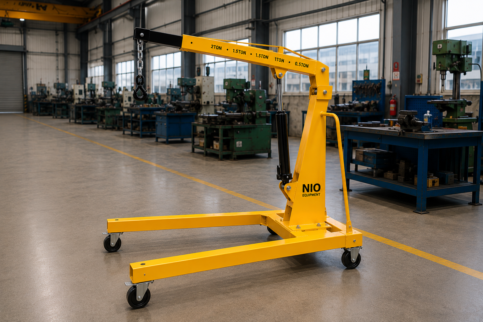
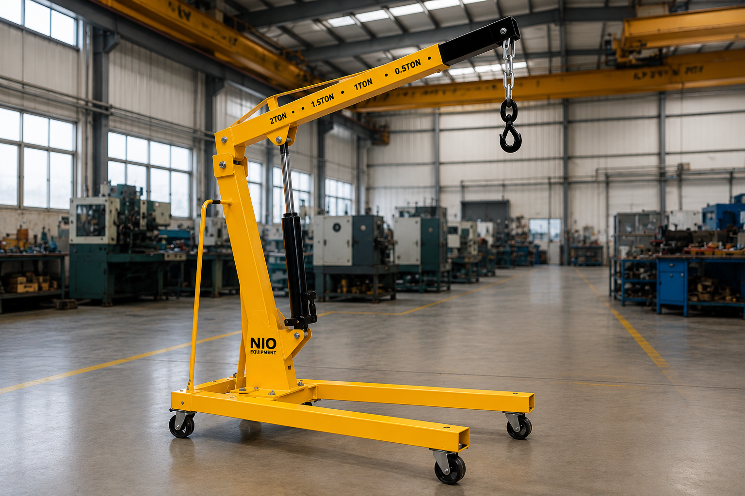
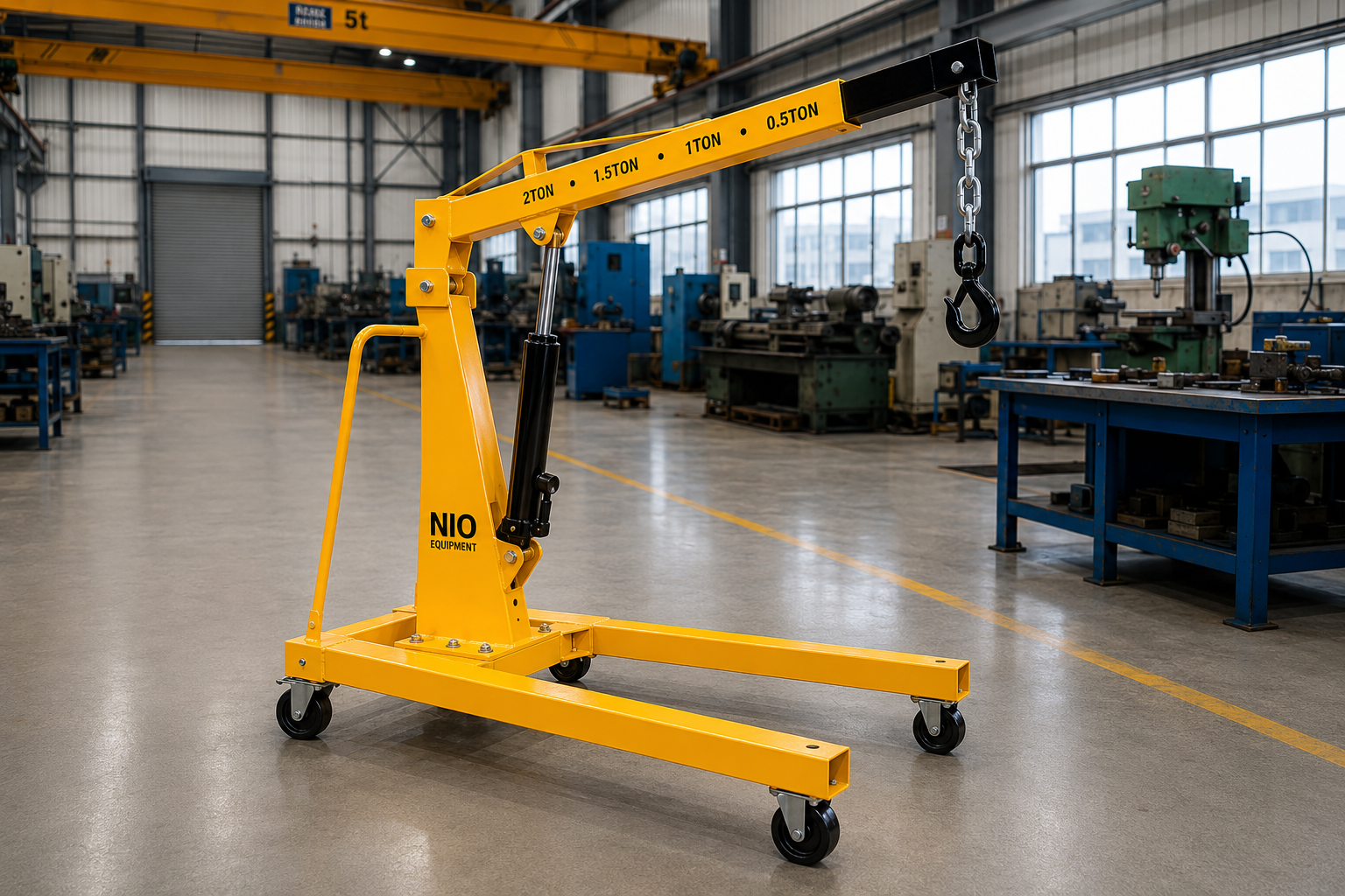
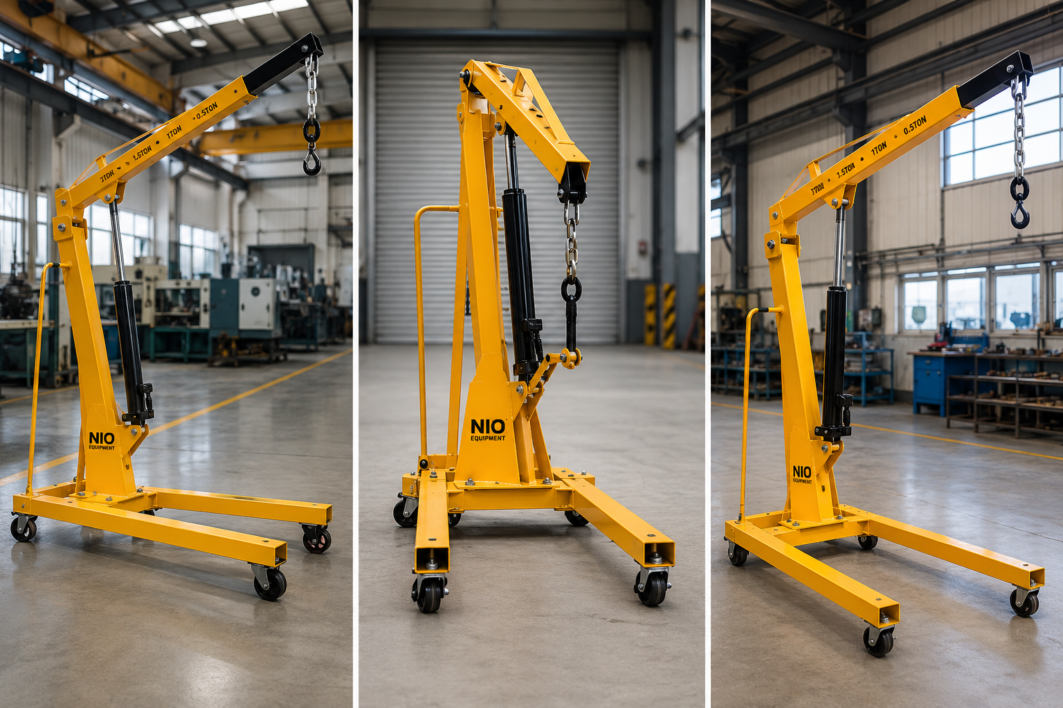

The Nio Equipment Floor Crane is a portable industrial lifting solution for handling machinery, dies, molds, motors, and maintenance components across workshops, warehouses, and production areas. Its fabricated steel chassis and stable mobile configuration support controlled lifting and accurate load positioning where fixed crane systems are impractical. Capacity, lift height, boom geometry, hydraulic operation, base arrangement, and finish can be customized to suit specific plant layouts and material handling requirements.
Specifications
| Capacity | 500 kg to 5,000 kg |
| Maximum Lift Height | 2,000 mm to 4,500 mm |
| Working Radius | 800 mm to 2,500 mm |
| Boom Adjustment | 3 to 5 working positions |
| Lifting System | Manual hydraulic or electric hydraulic |
| Boom Type | Single-stage or telescopic |
| Wheel Configuration | 4-wheel or 6-wheel heavy-duty castors |
| Structure | Fabricated structural steel |
Key Features
- Heavy-duty fabricated steel chassis
- Low-profile legs reach beneath machinery
- Compact footprint suits crowded shop floors
- Swivel hook aids accurate load alignment
- Serviceable hydraulic components simplify maintenance
- Mobile frame enables point-of-use lifting
- Rigid boom supports stable load handling
Optional Configurations
- Rated Load Capacity – Crane capacity can be engineered around the maximum lifted load, required boom position, load center, and intended operating frequency.
- Boom Geometry – Boom length, extension range, and working positions can be selected to provide the required hook reach and lifting envelope.
- Lift Actuation – Manual hydraulic or electric hydraulic lifting can be specified according to duty cycle, operator preference, and required productivity.
- Base Arrangement – Base width, leg length, and chassis geometry can be adapted around machinery footprints, pallets, workstations, and aisle constraints.
- Castor Configuration – Castor quantity, wheel material, diameter, and swivel arrangement can be selected for floor condition and maneuverability requirements.
- Protective Finish – Paint system, corrosion protection, and industrial color can be selected to suit indoor, workshop, or demanding plant environments.
Safety Features
- Overload Relief Valve
- Controlled Lowering Valve
- Positive Boom Locks
- Caster Parking Brakes
- Safety Latch Hook
- Stable Wide Base
Certifications & Standards
Use Cases
Product Resources
What Is a Floor Crane?
A Floor Crane is a portable industrial lifting device designed for precise handling of heavy machinery and components in workshop and factory settings. It facilitates lifting, positioning, and transporting loads without permanent installation. It is integral to internal material flow and maintenance operations across various manufacturing and industrial environments.
Working Principle of Floor Crane
The Floor Crane operates on a hydraulic lifting principle where manual or electric hydraulic power generates pressure to extend a cylinder, raising the boom and attached load. Controlled lowering is achieved by releasing hydraulic pressure through valves, enabling stable and precise vertical movement. The fabricated steel structure and adjustable boom geometry support load handling and positioning within defined working radii.
Step-by-Step Operation
- Position the crane adjacent to the load.
- Attach the load securely to the swivel hook with a safety latch.
- Activate the hydraulic system manually or electrically to raise the boom.
- Adjust the boom position to align the load accurately.
- Move the crane with the load to the required location.
- Lower the load gently using controlled hydraulic descent.
- Detach the load and return the boom to the lowered position.
Key Components
Safety Features - Detailed
- Overload relief valve prevents excessive loading
- Controlled lowering valve ensures smooth descent
- Positive boom locks secure boom position
- Caster parking brakes stabilize during loading
- Safety latch hook prevents accidental load release
- Stable wide base reduces tipping risk
- Serviceable hydraulic components simplify safety maintenance
- Boom adjustment stops to prevent overextension
- Operator proximity enables immediate response
- Manual or electric lifting control prevents runaway loads
- Structural steel construction ensures load integrity
- Periodic inspection recommended for hydraulic systems
- Clear visual load indicators assist safe use
Selection Factors
- Load capacity requirements
- Required lift height
- Working radius needed
- Boom geometry options
- Operating frequency
- Floor surface conditions
- Space availability for maneuvering
- Hydraulic lift type preference
- Safety feature requirements
- Load attachment method
- Environmental conditions
- Maintenance accessibility
- Custom base arrangement needs
- Operator skill level
- Corrosion protection necessity
Installation Requirements
- Level and stable floor surface
- Space clearance for boom movement
- Adequate aisle width for maneuvering
- Hydraulic system power availability
- Operator access and safety zones
- Secure parking brake application area
- Pre-commissioning functional tests
- Routine inspection scheduling
- Load attachment equipment availability
Maintenance Requirements
- Regular hydraulic oil inspection
- Hydraulic system leakage checks
- Lubrication of pivot points
- Inspection of boom locking mechanisms
- Caster wheel condition monitoring
- Overload valve functional testing
- Visual structural integrity checks
- Safety latch inspection
- Fastening torque verification
- Hydraulic hose condition assessment
- Controlled lowering valve checks
- Parking brake engagement testing
- Operational load tests
Advantages of Floor Crane
- Portable point-of-use lifting
- Supports flexible plant layouts
- No permanent installation required
- Positions hooks close to machinery
- Fits crowded maintenance spaces
- Reduces manual material handling
- Accelerates maintenance tasks
- Improves load positioning accuracy
- Minimizes equipment downtime
- Simplifies in-plant load transfer
- Heavy-duty structural construction
- Serviceable hydraulic components
- Adjustable boom configurations
- Multiple load capacity options
- Stable wide base design
- Caster parking brakes enhance stability
Limitations of Floor Crane
- Limited lift height compared to fixed cranes
- Requires flat and stable floor surfaces
- Not suitable for outdoor heavy weather use
- Capacity limited to 5,000 kg maximum
- Manual or electric hydraulic reliance
- Requires operator proximity to load
- Not designed for very high-frequency cycles
- Boom reach limited by physical design
- Relatively slower lifting speed versus powered tower cranes
- Periodic hydraulic maintenance mandatory
Common Alternatives to Floor Crane
Industry Applications
- Motor Installation Support
- Assembly Line Component Transfer
- Tooling Movement for Production
- Fixture Positioning at Workstations
- Die Change Handling
- Heavy Component Load Transfer
- Supports organized material flow
- Reduces manual load handling
- Improves load positioning precision
- Enhances assembly line coordination
- Speeds tooling changeover
- Minimizes floor space usage
- Machined Component Lifting
- Fabricated Part Transfer
- Assembly Fixture Handling
- Workshop Load Movement
- Tool Room Component Lifting
- Work-In-Progress Material Handling
- Supports material flow between work areas
- Reduces handling interruptions
- Improves load transfer safety
- Enables stable load positioning
- Facilitates flexible workflow layout
- Simplifies component assembly transfers
- Load Transfer Between Storage Levels
- Pallet Movement Within Aisles
- Order Preparation Load Handling
- Dispatch Area Load Positioning
- Receiving Area Material Transfer
- Workstation Load Alignment
- Enhances vertical inventory movement
- Reduces manual handling between levels
- Supports organized floor operations
- Improves load positioning accuracy
- Facilitates efficient goods consolidation
- Speeds loading and unloading
- Packaged Goods Movement
- Carton Transfer in Production
- Packaging Material Handling
- Product Load Positioning
- Dispatch Pallet Handling
- Storage Area Load Transfer
- Supports smooth material flow
- Improves coordination between levels
- Reduces handling interruptions
- Enhances load alignment precision
- Facilitates flexible production support
- Simplifies internal transport
- Packaged Product Transfer
- Carton Handling Between Floors
- Secondary Packaging Movement
- Production Material Alignment
- Container Load Positioning
- Operational Area Material Transfer
- Supports controlled material movement
- Enhances load positioning
- Reduces unnecessary manual handling
- Improves coordination across areas
- Facilitates smooth vertical transfer
- Simplifies internal logistics
- Receiving Area Load Transfer
- Storage Level Material Handling
- Dispatch Area Load Positioning
- Staging Area Component Movement
- Operational Floor Load Transfer
- Load Consolidation for Shipping
- Supports continuous goods movement
- Improves load handling coordination
- Reduces manual load transfer
- Enhances positioning accuracy
- Facilitates efficient staging operations
- Simplifies load consolidation
- Raw Material Vertical Transfer
- Component Movement Between Floors
- Work-In-Progress Material Handling
- Finished Goods Load Positioning
- Production Support Load Transfer
- Assembly Material Movement
- Supports organized material flow
- Reduces load handling downtime
- Improves vertical transport efficiency
- Facilitates efficient load positioning
- Enhances workflow flexibility
- Simplifies internal material transfer
Applications
Industries Served
Customization Options
How Floor Crane Compares to Alternatives
| Alternative | Key Difference |
|---|---|
| Hydraulic Floor Crane | Offers hydraulic lifting with enhanced control and higher load capacities compared to standard manual or electric floor cranes. |
| Mobile Floor Crane | Designed for greater maneuverability and transport over diverse shop floor layouts, often with lighter capacity than fixed floor cranes. |
| Jib Crane | Provides fixed or semi-fixed lifting with pivoting boom, ideal for repetitive lifting in defined areas rather than full shop mobility. |
| Wall Mounted Jib Crane | Mounts on walls to save floor space but limits load movement to the swing radius, unlike fully mobile floor cranes. |
| Pillar Mounted Jib Crane | Installed on a vertical pillar for localized lifting within a radius, not suitable for transporting loads across workshop floors. |
| Gantry Crane | Offers higher lifting height and spans wide areas, but usually requires more floor space and less flexibility in tight or crowded environments. |
| Electric Pallet Stacker | Focused on pallet handling and stacking loads vertically rather than versatile lifting and positioning of irregular or heavy components. |
| Hydraulic Lift Table | Primarily used for lifting and positioning loads at regulated heights but lacks mobility for load transport across multiple workstations. |
✓ When to Choose Floor Crane
- When frequent repositioning of heavy machinery or components is required in a workshop or production environment.
- When load weights fall within the 500 kg to 5,000 kg range and moderate lift heights up to 4,500 mm are necessary.
- When the work environment involves confined or crowded maintenance spaces requiring compact footprint and mobility.
- When flexible boom adjustment and multiple working positions are needed to accurately position loads close to machines or workstations.
- When the floor surface is flat and stable, enabling safe use of heavy-duty castor wheels for load mobility.
- When customization of crane capacity, boom geometry, or base arrangement is needed to fit specific operational or machinery footprints.
⚠ When Not to Choose Floor Crane
- When lifting heights exceed the maximum 4,500 mm capacity, consider gantry or overhead bridge cranes for taller lifts.
- When outdoor use in harsh weather or uneven surfaces is required; floor crane stability depends on flat, indoor floors.
- When continuous high-frequency lifting cycles are needed, alternatives such as electric hoists or automated stacker cranes may be more efficient.
- When very fast lifting speeds or precise automation is necessary, fixed or powered tower cranes may be preferable.
- When personnel transportation or load handling beyond crane lifting is needed, use forklifts or lift trucks instead.
- When handling loads exceeding the 5,000 kg capacity limitation, larger fixed cranes or gantry cranes should be evaluated.
Ideal Applications for Floor Crane
Who Uses This Product?
Request a Custom Quote - What We Need to Know
- What is the maximum load weight you need the floor crane to lift?
- What is the typical size and shape of the loads to be handled?
- What maximum lift height do you require for your operations?
- What is the typical working radius or reach needed from the crane's boom?
- Will the lifting system be manual hydraulic or electric hydraulic?
- What type of floor surface will the crane operate on?
- What is the expected frequency of lifting and transport cycles per shift or day?
- Are there any space constraints or specific footprint requirements at the installation site?
- Do you require specific boom adjustment positions or telescopic boom capabilities?
- Is corrosion protection or a special protective finish necessary for your operating environment?
Upgrade Options
Frequently Asked Questions
Why Choose NIO Equipment for Floor Crane
Trusted by manufacturers, warehouses and industrial facilities across India for quality, reliability and after-sales excellence.
- ✓Application-specific floor crane engineering
- ✓In-house structural fabrication capability
- ✓Site-responsive layout planning
- ✓Integrated hydraulic control expertise
- ✓Project documentation and commissioning support
- ✓Responsive after-sales service coordination
About This Product
The Floor Crane from Nio Equipment is a portable industrial lifting device for handling machinery, dies, molds, motors, gearboxes, pumps, tooling, and other heavy components. It combines a mobile fabricated steel frame, an adjustable boom, a hydraulic lifting system, and a swivel hook to support localized lifting, controlled positioning, and short-distance movement. Unlike a permanently installed crane, it can be brought to the point of work as production and maintenance requirements change.
The crane is suited to workshops, manufacturing plants, tool rooms, maintenance departments, assembly areas, and warehouses with flat, stable floors. Its compact footprint and low-profile legs help the chassis approach machinery and workstations where overhead handling systems or lift trucks may be impractical. Available application ranges cover capacities from 500 kg to 5,000 kg, maximum lift heights from 2,000 mm to 4,500 mm, and working radii from 800 mm to 2,500 mm.
Hydraulic Lifting Principle
Manual hydraulic or electric hydraulic power operates a lifting cylinder connected to the boom assembly. Hydraulic pressure extends the cylinder and raises the hook and attached load, while the controlled lowering valve regulates descent by releasing pressure in a managed manner. This operating principle provides the vertical control needed when aligning a component with a machine, foundation, fixture, or assembly location.
Boom geometry and load position directly affect rated capacity and stability. The selected capacity must therefore account for the maximum load, its center of gravity, the required working radius, and the boom position used during the lift. Positive boom locks and defined adjustment positions help maintain the selected lifting geometry.
Point-Of-Use Handling
A mobile floor crane supports work that would otherwise depend on repeated manual handling, a fixed crane, or coordination with a lift truck. Operators can position the crane beside a machine, attach a properly selected sling or load chain to the safety latch hook, raise the load, and align it with the receiving location. The mobile frame can then support controlled relocation along a clear, suitable travel path.
This capability is particularly relevant to maintenance and changeover work, where loads must be extracted from or introduced into confined equipment areas. The swivel hook assists with load alignment, while adjustable boom reach allows the hook to approach lifting points that are not directly above the chassis.
Flexible Plant Integration
Because the Floor Crane does not normally require a permanent runway, mast, wall mounting, or dedicated structural installation, it can support changing layouts and shared maintenance resources. It is suitable for moderate-duty workflows where lifting locations vary and where permanent crane coverage would be unnecessary or difficult to justify. Its value lies in flexible access rather than continuous automated movement or high-speed repetitive cycling.
The equipment should be applied within its defined lift height, working radius, floor, and capacity limits. Applications involving loads above 5,000 kg, lift heights above 4,500 mm, uneven outdoor surfaces, or continuous high-frequency operation require engineering review and may be better served by a gantry, overhead crane, hoist, or another purpose-designed handling system.
Applications
Machine Maintenance
During machinery servicing, the Floor Crane can raise guards, drive assemblies, tooling modules, and other removable components after they have been isolated and prepared for lifting. Low-profile legs can reach beneath suitable machinery clearances while the adjustable boom places the hook near the component lifting point. Controlled hydraulic lowering then helps place the removed assembly onto a service stand, pallet, or prepared work surface.
For reinstallation, the crane supports gradual alignment with mounting holes, shafts, couplings, and equipment interfaces. This reduces reliance on uncontrolled manual lifting and can shorten the time during which production equipment remains unavailable.
Motor And Gearbox Work
Industrial motors, gearboxes, pumps, and drive units often require lifting through restricted spaces during replacement or overhaul. A maintenance floor crane can be maneuvered beside the equipment, connected through approved lifting accessories, and used to raise the component clear of its mounting position. The swivel hook and hydraulic descent provide useful control when aligning shafts, base plates, and fastening points.
The required boom reach must be evaluated against the load center and surrounding obstructions. Where the standard base geometry cannot approach the machine, base width, leg length, and chassis arrangement can be reviewed for project-specific customization.
Die And Mold Handling
Tool rooms and production departments can use the crane to move dies, molds, and tooling assemblies between storage positions, service benches, and compatible machines. Multiple boom positions allow the hook reach to be selected for the loading location, while the rigid boom and fabricated chassis support stable handling within the rated load chart. The load must remain securely attached and balanced throughout extraction, travel, and placement.
In die change workflows, point-of-use lifting can reduce waiting for shared overhead equipment. It also supports controlled tooling placement where accurate alignment is more important than high travel speed.
Assembly Line Support
At assembly stations, the Floor Crane can present heavy components, fixtures, and production assemblies at the required installation point. It can move between cells as schedules change, making it useful where lifting demand is intermittent or distributed across several work areas. Operators can raise and lower the load incrementally to coordinate with fitters during component assembly.
The crane is especially relevant for low-volume, mixed-product, and maintenance-oriented workflows. For continuous automated cycles or very rapid repetitive handling, a fixed powered crane or dedicated manipulator may provide a more appropriate operating model.
Tool Room Transfers
Tool rooms handle dense, high-value loads that may be difficult to grip or position manually. The Floor Crane can transfer tooling, fixtures, machined components, and work-in-progress between benches, inspection areas, storage points, and production equipment. Its mobile frame enables shared use without dedicating permanent lifting equipment to every workstation.
Load attachment planning remains essential because the crane uses a hook-based interface. Slings, chains, lifting eyes, or custom accessories must be selected for the shape, balance, surface condition, and approved lifting points of the item.
Workshop Material Movement
Engineering and fabrication workshops can use a mobile floor crane for localized transfer of fabricated parts, machined components, assemblies, and maintenance equipment. Heavy-duty castors allow movement over a clear, level industrial floor, while parking brakes stabilize the crane during loading and unloading. A four-wheel or six-wheel arrangement can be selected according to maneuverability, floor condition, and application requirements.
Travel should be planned as a controlled, short-distance handling activity rather than unrestricted load transport. A clear route, suitable floor capacity, adequate aisle width, and controlled pedestrian access are required.
Warehouse Load Positioning
In warehouse receiving, staging, order preparation, and dispatch areas, the crane can position crated equipment, storage containers, operational components, and suitably secured loads. It can support lifting to storage or workstation elevations that fall within the selected hook height and working envelope. Palletized or packaged loads require an engineered attachment or lifting arrangement compatible with the swivel hook; the crane should not be treated as a substitute for pallet forks.
This application is useful when irregular or suspended loads cannot be handled conveniently by a pallet stacker. It can also reduce dependence on lift trucks for routine localized lifting in congested areas.
Production Material Flow
Manufacturing departments can apply the Floor Crane to selected raw materials, work-in-progress, finished assemblies, and production support loads. The crane can bridge short workflow gaps between machines, assembly benches, inspection points, and staging locations where a hook-supported lift is appropriate. Its mobility allows the handling resource to follow changing production priorities.
The load path must remain within a single suitable operating area and within the crane's lift envelope. It is not intended as a building-level goods lift or as equipment for transporting personnel.
Benefits
Reduced Manual Handling
Hydraulic lifting transfers the primary load-raising effort from workers to the crane's pump and cylinder system. This is valuable when motors, tooling, and machine components exceed practical manual handling limits or require controlled movement near equipment. Proper use can improve handling ergonomics and reduce exposure to lifting, carrying, and uncontrolled lowering tasks.
The benefit depends on correct load attachment and operator training. Workers still need to guide the operation safely without placing hands or bodies beneath a suspended load.
Improved Positioning Control
The adjustable boom, swivel hook, and controlled lowering system support precise load presentation. These characteristics help maintenance and assembly teams align equipment with shafts, foundations, fixtures, and mounting points without relying on abrupt manual movement. Improved control can also reduce the risk of contact damage to the load or receiving machine.
Three to five working boom positions can be provided within the supported configuration range. The selected position must remain consistent with the applicable rated capacity and required working radius.
Flexible Equipment Deployment
A portable floor crane can serve several workstations rather than remaining committed to one lifting zone. The castor-mounted chassis supports point-of-use deployment for maintenance, tooling changes, assembly, and workshop transfers. This flexibility is useful in plants with changing layouts, mixed production, or intermittent lifting requirements.
No major civil installation is normally required, which can simplify deployment compared with fixed jib or overhead crane systems. The operating floor, aisle clearances, and parking areas must nevertheless be assessed before use.
Maintenance Downtime Support
Bringing lifting capability directly to a failed machine or planned service location can reduce delays caused by waiting for shared handling equipment. The crane assists with removal, transfer, and reinstallation of serviceable components such as pumps, motors, and gearboxes. Accurate lowering can also make assembly and fastening activities more orderly.
Serviceable hydraulic components support maintainability over the equipment life. Routine inspection of oil, hoses, valves, pivots, locks, and wheels is necessary to preserve this operational benefit.
Application-Fit Configuration
Capacity, boom geometry, lift actuation, chassis dimensions, castors, and protective finish can be selected around the intended operating conditions. Matching these elements to load weight, load center, floor condition, aisle width, and duty cycle helps avoid an oversized general-purpose arrangement or an unsuitable compact design. Electric hydraulic actuation may support applications requiring greater productivity, while manual hydraulic operation can suit moderate, intermittent tasks.
Configuration flexibility also helps integrate the crane around pallets, machinery footprints, and crowded work areas. Every customized arrangement remains subject to engineering evaluation for stability, structural capacity, and safe access.
Technical Highlights
Rated Working Envelope
Supported Floor Crane configurations cover rated capacities from 500 kg to 5,000 kg, maximum lift heights from 2,000 mm to 4,500 mm, and working radii from 800 mm to 2,500 mm. These values define a configuration range rather than indicating that one crane carries its maximum capacity at every boom extension. Actual permissible loading depends on the selected model, boom position, load center, and engineered rating.
Boom adjustment is available in three to five working positions. Single-stage or telescopic boom arrangements may be selected to achieve the required balance between reach, hook height, compactness, and capacity.
Hydraulic Lift System
The lifting mechanism uses either a manual hydraulic pump or an electric hydraulic power arrangement to actuate the lifting cylinder. Manual actuation is suited to moderate-duty operation where simplicity and operator control are priorities, while electric hydraulic actuation can be specified according to cycle demand and productivity requirements. Hydraulic lines and functional components are integrated into the equipment rather than requiring an external plant hydraulic connection.
A controlled lowering valve regulates descent, and an overload relief valve protects against excessive hydraulic loading. These devices support safe operation but do not replace verification of the load weight and correct boom rating.
Fabricated Steel Structure
The load-supporting structure consists of a fabricated structural steel chassis and rigid boom assembly. A stable wide base distributes forces through the castors and floor while low-profile legs assist access beneath compatible machines, pallets, and workstations. Chassis geometry must maintain stability throughout the intended lifting envelope.
Structural selection considers load magnitude, reach, center of gravity, and operating frequency. Visual inspection for deformation, damaged weld areas, loose fasteners, or corrosion remains important because structural condition directly affects load integrity.
Hook And Boom Interface
A swivel hook with a safety latch provides the primary connection between the boom and the lifting accessory. Swivel movement helps orient the hook during attachment and alignment, while the latch reduces the likelihood of an unsecured sling leaving the hook throat. Appropriate slings, chains, lifting eyes, or engineered devices are still required for the actual load.
Positive boom locks secure the selected working position, and adjustment stops help prevent overextension. The operator must confirm full engagement of the locking mechanism before applying load.
Mobile Castor Arrangement
The crane may use a four-wheel or six-wheel heavy-duty castor arrangement depending on capacity and maneuverability requirements. Castor quantity, diameter, wheel material, and swivel pattern can be configured around the floor surface, turning space, and expected travel path. Parking brakes stabilize the chassis during attachment, lifting, and lowering.
Castors are intended for flat, stable industrial floors with a clear route. Uneven surfaces, debris, abrupt transitions, steep gradients, or outdoor terrain can impair stability and require a different handling solution.
Configurable Plant Fit
Boom length, extension range, base width, leg length, chassis layout, and protective finish can be adapted to suit the application. These options allow the crane to approach specific machine footprints, workstations, pallets, and restricted aisles while maintaining the required hook reach. Corrosion-protective paint systems may also be selected for demanding indoor plant conditions.
Customization should begin with a defined load case and site layout. Reducing base dimensions or increasing boom reach without engineering assessment can change stability and permissible capacity, so these decisions must be evaluated as an integrated crane configuration.
Industries Served
Automotive Manufacturing
Automotive plants can use the Floor Crane for motor installation, tooling movement, die changes, fixture positioning, and transfer of heavy production assemblies. These workflows frequently require a load to be placed close to a machine or assembly station without occupying the area with permanent lifting equipment. Adjustable reach and controlled lowering support alignment during changeover and maintenance work.
Capacity and base geometry can be selected around tooling weights, workstation access, and line-side space. For continuous production lifting, the duty requirement should be reviewed to determine whether electric hydraulic actuation or a fixed handling system is more appropriate.
Engineering Workshops
Engineering workshops handle machined components, fabricated parts, assembly fixtures, tool room equipment, and work-in-progress with varied shapes and lifting points. A workshop floor crane can move between machines, inspection stations, benches, and service areas as individual jobs progress. This supports flexible layouts where lifting demand changes from one project to another.
A configurable boom and chassis help address restricted machine access. Suitable load chains, slings, and lifting attachments remain necessary for irregular components.
Die And Mold Operations
Die and mold facilities require controlled handling because tooling is dense, valuable, and often positioned within machines with limited clearance. The Floor Crane can support mold servicing, die transfer, tooling movement, and placement onto prepared storage or maintenance locations. Hydraulic lowering helps technicians align tooling without relying on abrupt manual adjustment.
The maximum load and its center of gravity must be confirmed at the required boom extension. Where die handling is frequent or involves loads above 5,000 kg, a larger fixed or gantry crane should be evaluated.
Metal Fabrication
Fabrication operations can use the crane to handle welded assemblies, machined fabrications, fixtures, pumps, and workshop equipment. Mobility allows the same lifting resource to support cutting, welding, machining, inspection, and assembly areas, provided the travel route remains clear and level. The hook interface is well suited to loads with approved lifting eyes or properly arranged slings.
Protective finishes can be selected for demanding indoor workshop environments. Dust, debris, and floor contamination should still be controlled to protect hydraulic components and castor performance.
Warehousing And Logistics
Warehousing and distribution operations can apply the crane in receiving, staging, storage, order preparation, and dispatch areas for crated machinery, containers, operational equipment, and suitably rigged packaged loads. It can place loads at workstation or storage elevations within the selected lift range and assist with localized consolidation. This is useful where a suspended load interface is more appropriate than pallet forks.
The crane does not replace a lift truck for general pallet transport or long travel distances. Warehouse applications should define the load attachment, aisle width, floor condition, and interaction with pedestrian and vehicle routes.
Process And Consumer Plants
FMCG and pharmaceutical facilities can use a Floor Crane for packaged products, containers, secondary packaging equipment, production support loads, and maintenance components. Typical work includes positioning equipment near packaging lines, moving operational loads between nearby work areas, and supporting planned maintenance. Controlled handling can reduce unnecessary manual transfers while keeping the equipment portable.
Configuration should reflect cleanliness expectations, floor conditions, load protection needs, and exposure to corrosive agents. A suitable protective finish may be specified, but the crane is primarily intended for controlled indoor industrial environments rather than hygienic or hazardous duties unless specifically engineered.
Why Choose NIO Equipment
Application-Specific Engineering
Nio Equipment approaches Floor Crane selection around the actual load case rather than capacity alone. Engineering review can consider load weight, center of gravity, hook height, working radius, boom position, operating frequency, floor condition, and available maneuvering space. This helps align the crane's structure and lifting envelope with the intended maintenance, production, or warehouse workflow.
Consultation is particularly important for unusual load geometry, restricted base access, multiple working heights, specialized attachments, or requirements near the upper limits of the supported range. Applications beyond 5,000 kg or 4,500 mm can also be reviewed to determine whether another crane type is more suitable.
Configurable Crane Design
Nio Equipment can configure rated capacity, boom geometry, manual or electric hydraulic actuation, base arrangement, castor selection, boom positions, and protective finish. These variables allow the Floor Crane to be adapted around machinery footprints, pallets, aisles, floor surfaces, and operator preferences. Configuration remains subject to engineering evaluation so that reach, mobility, and stability are considered together.
Options such as a telescopic boom, six-wheel heavy-duty castor arrangement, customized leg length, or corrosion-resistant finish are selected according to project needs rather than assumed to be standard. This distinction gives procurement teams a clearer basis for comparing technically suitable proposals.
Manufacturing And Hydraulic Capability
Nio Equipment combines structural fabrication capability with experience in material handling and hydraulic lifting equipment. This supports coordinated design of the steel chassis, boom, hydraulic controls, load interface, and mobility arrangement. Serviceable hydraulic components and practical access considerations can also be incorporated into the equipment configuration.
The result is a manufacturing-oriented approach that considers how the crane will be operated, inspected, and maintained in an industrial facility. It avoids treating the Floor Crane as an isolated lifting device without reference to the surrounding workflow.
Project Lifecycle Support
Nio Equipment provides application-based configuration, installation support, commissioning support, project documentation, and after-sales service coordination across India. These capabilities assist engineering and procurement teams in moving from initial load data through site review, configuration, operational release, and maintenance planning. Commissioning support can also help verify functional controls and operator understanding for the supplied arrangement.
A productive RFQ should include the maximum load, load dimensions and center of gravity, required lift height, working radius, preferred actuation, boom positions, floor details, aisle constraints, attachment needs, and environmental conditions. Providing this information enables Nio Equipment to evaluate the Floor Crane against the complete application rather than relying on a nominal capacity request.
Installation Guide
Site And Floor Assessment
Although the Floor Crane is portable and normally requires no fixed foundation, its operating surface is a critical part of safe deployment. The floor should be level, stable, clean, and suitable for the combined crane and load forces transmitted through the castors. Surface joints, slopes, damaged areas, debris, and level changes should be reviewed before selecting the travel path.
Outdoor locations, uneven floors, or harsh weather exposure fall outside the preferred operating conditions. If these conditions cannot be avoided, Nio Equipment should evaluate whether a customized arrangement or alternative crane type is required.
Working Envelope Planning
Site planning should confirm the required lift height, horizontal reach, hook access, and boom clearance around machinery, walls, services, and overhead obstructions. Adequate space is needed for the chassis legs, boom movement, operator position, load rotation, and safe attachment work. The assessment should consider every stage from initial pickup through travel and final placement.
Base width and leg length can be customized around machinery footprints and aisle restrictions, subject to engineering evaluation. Unusual load geometry or an offset center of gravity should be disclosed because it can influence boom selection, stability, and the required attachment method.
Material Flow Layout
The proposed operating route should be mapped between pickup, service, staging, and delivery locations. Aisles must provide enough width for the crane, load, and operator without contact with structures, stored materials, or active production equipment. Pedestrian and vehicle interaction should be controlled through site procedures and clearly defined lifting zones.
Loading and unloading locations should provide space to apply parking brakes and position the load without side pulling. If several landing elevations are required, each height must fall within the selected boom and lift envelope.
Power And Access
Manual hydraulic models require no external power connection during routine operation. Electric hydraulic configurations need a suitable electrical supply for the selected power unit, with connection details established in project documentation. Power routing should avoid trip, crush, and snag hazards and should permit safe isolation for maintenance.
Access must be retained around the pump, cylinder, reservoir, valves, hoses, boom pivots, and castors. Parking space should allow the boom to be lowered and the crane secured when not in use.
Commissioning And Testing
Before operational release, the assembled crane should undergo functional checks covering hydraulic lifting and lowering, boom lock engagement, hook latch operation, castor movement, parking brakes, and visible structural condition. The overload relief and controlled lowering functions should be verified in accordance with the equipment documentation. Operational load testing should be performed using an approved procedure and controlled test area.
Commissioning should also confirm that operators understand the load ratings, boom positions, attachment practices, and travel restrictions. Nio Equipment can provide installation and commissioning support where required for the supplied configuration.
Maintenance Guide
Routine Condition Checks
Pre-use and periodic inspections should identify hydraulic leaks, damaged components, loose fasteners, abnormal boom movement, castor defects, and deterioration of the hook or latch. The crane should move and lift smoothly without unusual noise, vibration, binding, or uncontrolled descent. Any condition that may affect stability or load retention requires the equipment to be removed from service for evaluation.
Inspection frequency should reflect operating conditions, load severity, environmental exposure, and usage. Records can help maintenance teams identify recurring wear and plan corrective work before a functional failure occurs.
Hydraulic System Care
Hydraulic oil condition and level should be checked as recommended in the equipment documentation. Hoses, fittings, the lifting cylinder, pump, reservoir, and control valves should be inspected for seepage, abrasion, cracking, damaged seals, or loose connections. Cleanliness is important because contamination can impair valve performance and accelerate internal wear.
The controlled lowering valve and overload relief valve require periodic functional verification. Hydraulic components should be serviced only by competent personnel using suitable isolation and load-support procedures.
Boom And Frame Inspection
The fabricated frame, boom, pivots, adjustment holes, locking components, and weld areas should be examined for deformation, cracking, corrosion, impact damage, or excessive play. Positive boom locks must engage fully and remain free from wear that could compromise retention. Fastening torque should be verified where specified by the equipment documentation.
Pivot points require appropriate lubrication to reduce friction and wear. Lubricants should be applied without contaminating brakes, castor treads, the hook interface, or floor surfaces.
Castor And Brake Service
Castor wheels should rotate and swivel freely without flat spots, damaged tread, bearing looseness, or material buildup. Parking brakes must engage positively and hold the crane stationary during the defined loading and unloading condition. Wheel damage can increase push effort, impair steering, and introduce instability during load movement.
Wheel material and condition should remain suitable for the actual floor. Replacement castors must match the engineered load and geometry requirements rather than being selected solely by physical size.
Hook And Safety Devices
The swivel hook, safety latch, load chain, boom stops, and adjustment locks should be checked for wear, distortion, restricted movement, or unauthorized repair. The latch must close correctly, but it should not be treated as the primary means of retaining an incorrectly seated sling. Damaged lifting accessories should be quarantined under the site's lifting equipment procedure.
Periodic operational load tests and safety-device checks help confirm continued function after servicing or extended use. Maintenance should follow the supplied documentation and consider the crane's actual duty and environment.
Safety Guide
Operator Competence
Only trained and authorized personnel should operate the Floor Crane. Training should cover hydraulic controls, capacity interpretation, boom adjustment, parking brake use, lifting accessory selection, travel planning, and response to abnormal conditions. Operators must understand that mobility does not remove the hazards associated with a suspended load.
A pre-use check should be completed before lifting. The operating area should be controlled so that people remain clear of the boom, chassis, moving load, and potential crush zones.
Capacity And Load Control
The load weight, center of gravity, lifting points, and attachment method must be established before the crane is connected. Capacity varies with boom geometry, so the rating applicable to the selected reach and position must not be exceeded. The overload relief valve provides protective hydraulic control but is not a substitute for load planning.
Loads should be raised vertically without dragging, side pulling, or using boom movement to free a jammed component. A short trial lift can be used to confirm balance and attachment security before continuing.
Stable Lifting Practice
The crane should be positioned on a flat, stable floor with its base correctly aligned to the load. Parking brakes should be applied during attachment, lifting, positioning, and lowering as required by the operating procedure. The safety latch hook, positive boom locks, stable wide base, and controlled lowering valve work together to support secure handling.
Hands, feet, and other body parts must remain outside pinch points and away from beneath the suspended load. Operators should use controlled guidance methods rather than attempting to restrain a swinging or unstable load manually.
Safe Travel Path
Before moving a loaded crane, the route should be checked for debris, slopes, floor damage, door thresholds, tight corners, pedestrians, and vehicle traffic. The load should be kept in a stable travel position consistent with the equipment instructions and should not obstruct operator awareness. Sudden starts, abrupt turns, and impact with structures can shift the center of gravity.
The crane is intended for clear indoor industrial floors and moderate-duty movement. It should not be used on unsuitable outdoor ground, for personnel transport, or for loads beyond its engineered lifting envelope.
Fault And Maintenance Isolation
If hydraulic leakage, uncontrolled movement, brake failure, damaged structure, or incomplete boom lock engagement is observed, lifting should stop and the equipment should be secured. In a hydraulic fault, personnel must remain clear while the load is stabilized under the site's emergency procedure. No one should work beneath a suspended load or rely solely on hydraulic pressure to support it during maintenance.
Maintenance requires appropriate isolation, mechanical load support, and control of stored hydraulic energy. Unauthorized welding, drilling, boom extension, counterweight changes, valve adjustment, or chassis modification can affect capacity and stability and should not be undertaken.


