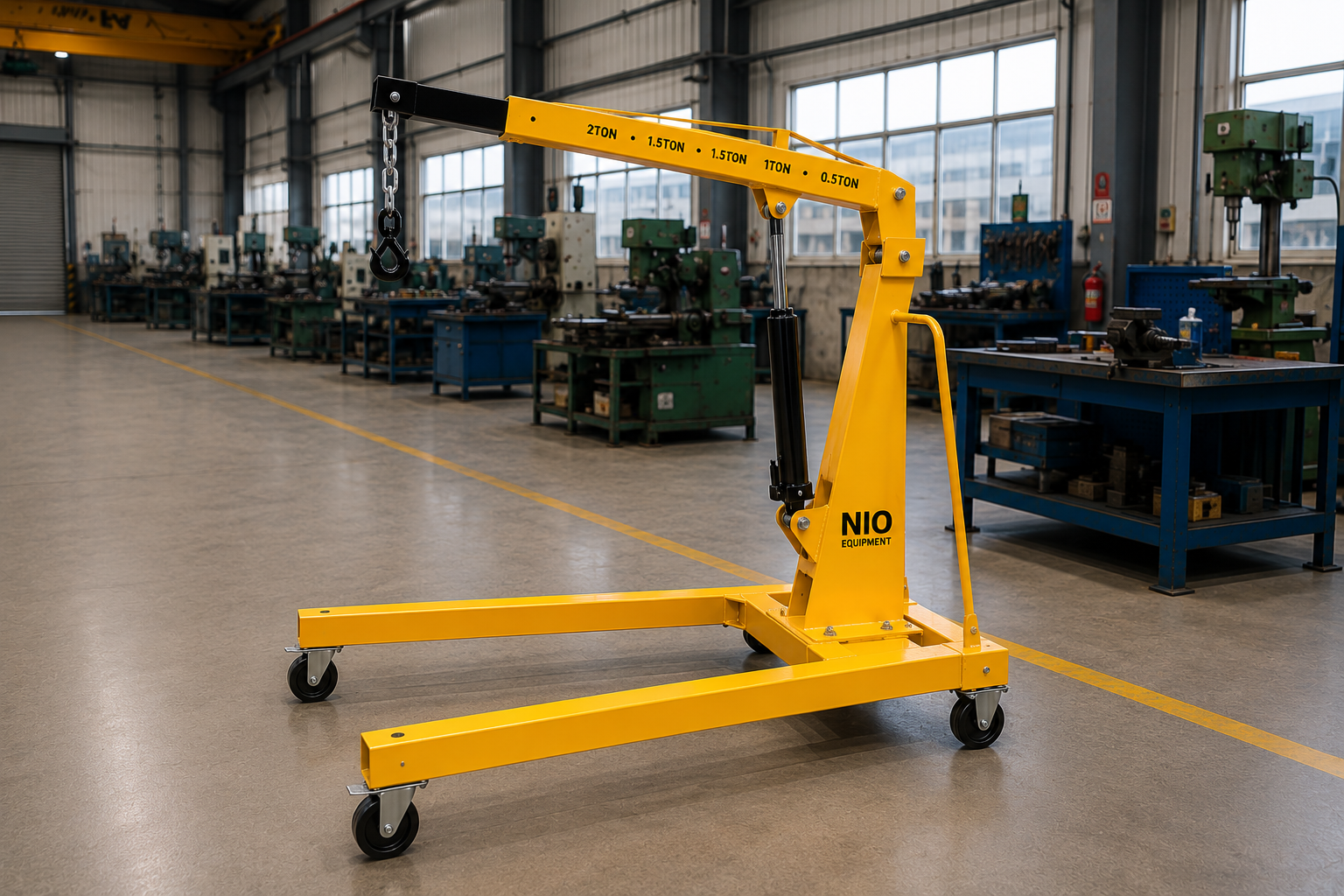
The Nio Equipment Mobile Floor Crane is a portable industrial lifting solution for raising, positioning, and moving machinery, dies, motors, and heavy components around factories and workshops. Its fabricated steel frame and mobile castor-mounted chassis provide dependable load support with practical point-of-use maneuverability. Boom geometry, lifting method, capacity, base layout, counterweight arrangement, and finish can be configured to suit maintenance, installation, assembly, and material handling requirements.
Specifications
| Rated Capacity | 500 kg to 5,000 kg |
| Maximum Lift Height | 2.0 m to 4.5 m |
| Boom Length | 1.2 m to 3.0 m |
| Working Radius | 0.8 m to 2.5 m |
| Boom Positions | 3 to 5 adjustable positions |
| Boom Configuration | Single-stage or telescopic steel boom |
| Lifting Operation | Manual hydraulic, electric-hydraulic, manual chain hoist, electric wire rope hoist |
| Mobility | Heavy-duty fixed and swivel industrial castors |
| Structure | Fabricated structural steel frame |
| Surface Finish | Industrial painted or corrosion-protected finish |
Key Features
- Mobile chassis enables point-of-use lifting
- Heavy-duty fabricated steel frame
- Reinforced boom supports demanding load cycles
- Compact footprint improves workshop maneuverability
- Hook-based handling suits varied components
- Stable base supports controlled load movement
- Serviceable lifting components simplify maintenance
Optional Configurations
- Load Capacity – Rated lifting capacity can be selected to match machinery, dies, motors, tooling, and other application-specific industrial load requirements.
- Boom Geometry – Boom length, lift height, working radius, and adjustment positions can be configured around machine access and load placement requirements.
- Lifting System – Select manual hydraulic, electric-hydraulic, chain hoist, or wire rope lifting according to load frequency and positioning needs.
- Base Arrangement – Base width, leg profile, and overall footprint can be adapted for aisle clearance, machine access, and available operating space.
- Counterweight Configuration – Counterweight layout can be engineered to balance required lifting geometry while supporting stability and practical movement around the facility.
- Surface Finish – Industrial paint color and corrosion-protection treatment can be selected for indoor, outdoor, humid, or application-specific operating environments.
Safety Features
- Overload Protection
- Controlled Lowering Valve
- Hydraulic Hose Protection
- Mechanical Boom Lock
- Castor Parking Brakes
- Safety Latch Hook
Certifications & Standards
Use Cases
Product Resources
What Is a Mobile Floor Crane?
The Mobile Floor Crane is a portable lifting device designed for precise handling and positioning of industrial loads such as machinery, dies, and tooling. It operates within workshops, factories, and warehouses to facilitate efficient material handling and equipment maintenance without fixed installation constraints. This crane supports flexible workflows by enabling short-distance load movement at the point of use.
Working Principle of Mobile Floor Crane
The Mobile Floor Crane uses a hydraulic lifting system or manual mechanical hoist to convert applied force into controlled vertical movement. Hydraulic pressure generated by a pump actuates a cylinder or hoist, lifting the boom and load smoothly. The fabricated steel structure ensures stability while the heavy-duty castors enable mobility between work areas, supporting flexible load positioning without permanent mounting.
Step-by-Step Operation
- Position the crane near the load to be lifted.
- Secure the load using the hook and safety latch.
- Engage the hydraulic or hoist lifting mechanism.
- Raise the load to the required height within rated capacity.
- Maneuver the crane base on castors to the desired location.
- Lower the load carefully, controlling descent speed hydraulically.
- Release the load and retract the boom to rest position.
Key Components
Safety Features - Detailed
- Overload protection prevents exceeding capacity
- Controlled lowering valve ensures smooth descent
- Hydraulic hose protection reduces leak risk
- Mechanical boom lock secures extended boom
- Castor parking brakes stabilize crane position
- Safety latch hook prevents load slippage
- Stable base reduces tipping hazards
- Load capacity customization improves safety margin
- Adjustable boom positions avoid overstretching
- Regular maintenance maintains safety system integrity
- Operator training reduces misuse and accidents
- Clear operational zones prevent collisions
- Inspection of lifting components ensures reliability
- Emergency stop controls depend on configuration
Selection Factors
- Rated load capacity needs
- Maximum lift height requirement
- Boom length and geometry
- Operating workspace dimensions
- Type of lifting system preferred
- Frequency of load handling tasks
- Load characteristics and attachment types
- Floor surface condition
- Environmental exposure considerations
- Safety feature needs
- Maintenance accessibility
- Custom configurations required
- Mobility and maneuvering space
- Infrastructure for hydraulic power supply
- Operator training and skill level
Installation Requirements
- Level and stable concrete floor
- Sufficient clearance around crane
- Adequate space for boom extension
- Access for hydraulic power or manual operation
- Operator training before commissioning
- Safety signage and operational zones
- Clear floor paths for castor movement
- Periodic service access area
- Proper lighting in operating area
- No fixed mounting required
Maintenance Requirements
- Regular hydraulic oil level check
- Inspection of hydraulic hoses and fittings
- Lubrication of pivot points and joints
- Safety device and latch inspection
- Checking overload protection functionality
- Structural frame inspection for cracks
- Castor wheel condition and fastening checks
- Routine operational function tests
- Brake system verification on castors
- Cleaning of boom and mechanical parts
- Monitoring for hydraulic leaks
- Fastener torque inspections
- Inspection of lifting hooks and chains
- Electrical component checks if applicable
Advantages of Mobile Floor Crane
- Portable point-of-use lifting
- Heavy-duty steel construction
- Adjustable boom length and height
- Supports varied load handling tasks
- No permanent mounting required
- Improves machinery access safety
- Hydraulic and mechanical lifting options
- Compact footprint for tight spaces
- Enhances workshop workflow flexibility
- Reduces manual handling risks
- Enables quick load repositioning
- Minimizes equipment downtime
- Serviceable components simplify repairs
- Stable base for controlled movement
- Customizable load capacity options
Limitations of Mobile Floor Crane
- Limited lifting capacity up to 5,000 kg
- Maximum lift height restricted to 4.5 m
- Requires smooth, level floor surfaces
- Not suitable for long-distance load travel
- Manual or semi-powered operation only
- Boom reach limited to 3.0 m
- Dependent on operator skill for positioning
- Hydraulic maintenance required periodically
- Not designed for outdoor harsh environments
- Space constraints may limit maneuverability
- Requires routine inspection for safety compliance
Common Alternatives to Mobile Floor Crane
Industry Applications
- Automotive Component Transfer
- Assembly Line Material Handling
- Tool and Fixture Positioning
- Production Support Material Movement
- Machine Installation Assistance
- Motor Replacement Operations
- Supports organized material flow
- Reduces manual handling risks
- Improves load positioning accuracy
- Minimizes production equipment downtime
- Enhances workshop maneuverability
- Speeds component transfer processes
- Fabricated Part Movement
- Machined Component Transfer
- Tool and Fixture Handling
- Workshop Load Relocation
- Assembly Line Tool Positioning
- Production Material Shifting
- Facilitates smooth material flow
- Reduces handling interruptions
- Enhances coordination between areas
- Improves load stability and control
- Supports flexible workshop workflows
- Speeds component repositioning
- Storage Level Inventory Transfer
- Mezzanine Load Handling
- Receiving Area Material Movement
- Dispatch Area Load Positioning
- Order Preparation Load Transfer
- Warehouse Floor Material Flow
- Supports vertical inventory movement
- Reduces manual lifting efforts
- Improves material handling safety
- Enhances coordination between zones
- Minimizes load handling delays
- Increases operational floor space efficiency
- Carton Transfer Between Areas
- Crate Positioning in Production
- Packaged Goods Handling
- Packaging Material Movement
- Production Support Material Transfer
- Finished Goods Load Shifting
- Facilitates smooth material flow
- Improves coordination between levels
- Reduces unnecessary manual handling
- Supports flexible load positioning
- Minimizes handling damage
- Speeds material transfer tasks
- Packaged Product Movement
- Carton Relocation
- Container Handling
- Secondary Packaging Transfer
- Production Support Material Flow
- Operational Area Load Positioning
- Ensures controlled material movement
- Supports organized operational flow
- Reduces manual handling needs
- Improves load stability
- Facilitates safer goods transfer
- Enhances workflow continuity
- Receiving Area Load Transfer
- Storage Level Material Movement
- Dispatch Area Load Positioning
- Operational Floor Load Handling
- Staging Area Load Movement
- Warehouse Floor Material Transfer
- Supports continuity of goods movement
- Improves coordination between areas
- Reduces manual handling interruptions
- Enhances load control and safety
- Facilitates efficient load positioning
- Optimizes operational floor usage
- Raw Material Transfer
- Component and Assembly Handling
- Work-in-Progress Movement
- Finished Goods Loading
- Production Support Material Positioning
- Machine and Tooling Relocation
- Enables organized material flow
- Reduces handling delays
- Supports vertical goods movement
- Improves load placement accuracy
- Minimizes equipment downtime
- Enhances workflow flexibility
Applications
Industries Served
Customization Options
How Mobile Floor Crane Compares to Alternatives
| Alternative | Key Difference |
|---|---|
| Floor Crane | Floor Cranes typically have fixed bases and may lack the mobility of the Mobile Floor Crane, making them better suited for semi-permanent lifting tasks. |
| Hydraulic Floor Crane | Hydraulic Floor Cranes offer enhanced lifting power and smoother hydraulic operation but generally have less flexibility in mobility compared to manual or semi-powered Mobile Floor Cranes. |
| Jib Crane | Jib Cranes provide fixed or semi-fixed pivoting lifting within a defined radius, suitable for repetitive point lifts but less adaptable to workshop-wide load transfers than Mobile Floor Cranes. |
| Wall Mounted Jib Crane | Wall Mounted Jib Cranes require building-mounted installation, limiting portability but offering dedicated lifting at fixed points, unlike the fully mobile Mobile Floor Crane. |
| Pillar Mounted Jib Crane | Pillar Mounted Jib Cranes offer a fixed rotation point with stable load support but lack the flexible positioning capability of Mobile Floor Cranes that can transport loads across workshop areas. |
| Gantry Crane | Gantry Cranes provide overhead lifting capability with a larger working range but require more installation space and infrastructure than the compact, floor-based Mobile Floor Crane. |
| Electric Pallet Stacker | Electric Pallet Stackers are specialized for palletized load movement and stacking but are less suited for irregular or heavy component positioning tasks where Mobile Floor Cranes excel. |
| Overhead Crane | Overhead Cranes provide high-capacity, long-span lifting in fixed installations, contrasting with the Mobile Floor Crane’s compact, flexible, and portable usage within workshops. |
✓ When to Choose Mobile Floor Crane
- When lifting and transporting machinery or components within a workshop without fixed lifting points.
- When a range of lifting heights up to 4.5 meters and varied boom lengths are needed for flexible load positioning.
- When manual hydraulic or electric-hydraulic lifting systems are preferable for moderate frequency lifting tasks reducing downtime.
- When space constraints require a compact footprint allowing maneuverability around equipment and in tight aisles.
- When point-of-use heavy load handling is needed without permanent installation or dedicated overhead lifting infrastructure.
- When application-specific load capacity, boom geometry, and base arrangements must be customized to fit diverse factory layouts.
⚠ When Not to Choose Mobile Floor Crane
- When lifting loads exceeding 5,000 kg where overhead or gantry cranes provide necessary higher capacity and safety.
- When load travel over longer distances or facility-wide transfer is required, favoring overhead cranes or gantry systems.
- Where vertical lift heights above 4.5 meters are needed, making jib or overhead cranes more suitable.
- For outdoor or harsh environment applications requiring weatherproof or heavy-duty structural cranes designed for external use.
- When automated or highly repetitive load handling with integrated controls is needed, suggesting electric or overhead crane systems with automation.
- If the floor surface is uneven or unsuitable for heavy-duty castor movement, fixed jib or floor cranes may ensure safer operations.
Ideal Applications for Mobile Floor Crane
Who Uses This Product?
Request a Custom Quote - What We Need to Know
- What is the maximum load weight you need the Mobile Floor Crane to lift?
- What are the typical load dimensions and shapes to be handled by the crane?
- What is the required maximum lift height for your application?
- Which lifting system do you prefer: manual hydraulic, electric-hydraulic, manual chain hoist, or electric wire rope hoist?
- What is the expected frequency of lifting operations per shift or day?
- What are the spatial constraints or available floor space for crane operation and maneuvering?
- Will the crane be used indoors only, or are there environmental considerations like humidity or exposure to elements?
- Do you require adjustable boom positions or telescopic boom geometry for load positioning?
- Are there specific base arrangement or counterweight configuration needs for aisle clearance or stability?
- What type of floor surface will the crane operate on and what is its condition?
Upgrade Options
Frequently Asked Questions
Why Choose NIO Equipment for Mobile Floor Crane
Trusted by manufacturers, warehouses and industrial facilities across India for quality, reliability and after-sales excellence.
- ✓Application-specific crane engineering
- ✓In-house design and manufacturing
- ✓Custom load handling geometry
- ✓Industrial site planning support
- ✓Flexible lifting control integration
- ✓Dedicated after-sales service support
About This Product
The Mobile Floor Crane from Nio Equipment is a portable industrial lifting device for raising, positioning, and moving machinery, dies, motors, tooling, and heavy components at the point of use. Its mobile chassis allows the crane to serve multiple work areas without permanent mounting or dedicated overhead lifting infrastructure. It is particularly relevant where maintenance and production teams need controlled lifting close to machines, assembly stations, tool rooms, or warehouse staging areas.
Point-Of-Use Load Handling
Unlike fixed lifting equipment, the crane can be moved into position near a load and aligned with the required lifting point. A hook with a safety latch connects to a suitable sling or attachment, after which the selected hydraulic or hoist mechanism raises the load within the rated capacity and configured working radius. The load can then be positioned locally or transported over a short, clear route on the crane's industrial castors.
Operating Principle
Depending on configuration, lifting may be performed by a manual hydraulic system, electric-hydraulic system, manual chain hoist, or electric wire rope hoist. Hydraulic versions use pump-generated pressure to actuate the lifting mechanism, while controlled lowering supports a smooth and deliberate descent. Manual and powered hoist arrangements provide alternative lifting control for different load characteristics, operating frequencies, and positioning requirements.
Workshop Workflow Role
The Mobile Floor Crane supports workflows that would otherwise require several people, temporary lifting arrangements, or access to a fixed crane. Typical tasks include removing a motor from a machine, positioning a gearbox for installation, presenting tooling to an assembly point, and transferring a component between adjacent work areas. Adjustable boom geometry helps the hook reach around machine frames or into restricted service areas while remaining within the engineered load chart.
Suitable Operating Environment
The crane is intended primarily for indoor industrial environments with smooth, level floors and clear maneuvering space. Workshops, factories, tool rooms, maintenance departments, and warehouses can use it for moderate-duty, short-distance handling where compact equipment access is important. Corrosion-protected finishes may be specified for particular conditions, but the equipment is generally not intended for harsh outdoor service or travel over uneven surfaces.
Applications
Machine Maintenance
Maintenance teams can position the crane beside production machinery to remove and reinstall heavy service components. The adjustable boom can be selected around the required height, radius, and machine access envelope, allowing motors, guards, pumps, or assemblies to be lifted clear in a controlled manner. Mobile deployment also reduces dependence on a permanently installed lifting point for routine servicing.
Die And Mold Handling
In die and mold operations, the crane can support die changes, tool removal, and controlled placement onto suitable stands or transfer equipment. Hook-based handling accommodates appropriately rigged loads with shapes that may not suit conventional pallet-handling equipment. Boom reach, base profile, load center, and available clearance should be reviewed because die weight and geometry directly affect stability.
Motor And Gearbox Installation
Motors, gearboxes, pumps, and related drive components often require accurate alignment during installation or replacement. The Mobile Floor Crane allows the suspended component to be raised and presented near its mounting position while technicians guide final placement. Controlled lowering assists with bolt-hole alignment and reduces the risk of impact damage to shafts, housings, and machine interfaces.
Tool Room Operations
Tool rooms can use the crane to relocate heavy jigs, fixtures, dies, and production tooling between storage, inspection, maintenance, and issue areas. Its compact mobile base supports access where an overhead crane may not be available or practical. Suitable rigging and a clear travel path remain necessary when moving irregularly shaped tooling.
Assembly Line Support
The crane can present components, fixtures, or subassemblies at an assembly station when handling by hand would be unsafe or inefficient. Its adjustable boom positions allow the lifting geometry to be adapted to different workstations, provided the selected position remains within the applicable capacity. This makes the equipment useful for production support tasks that vary in location or component type.
Component Transfer
Fabricated parts, machined components, and work-in-progress assemblies can be transferred over short distances between adjacent production areas. The stable base and heavy-duty castors support controlled local movement on suitable floors, while the hook interface enables handling of loads with approved lifting points. The crane is not intended as a substitute for long-distance transport equipment.
Warehouse Load Positioning
Within receiving, staging, storage, and dispatch zones, the crane can position appropriately rigged crates, containers, packaged goods, or maintenance loads. It is most useful where the load must be lifted from above or placed with greater precision than pallet equipment can provide. Palletized loads require a compatible and engineered attachment arrangement rather than direct unsupported hook handling.
Plant Equipment Relocation
The Mobile Floor Crane can assist with positioning smaller machines, supporting equipment, and heavy plant components during layout changes or installation work. A project review should confirm load weight, center of gravity, lifting points, route clearance, and floor condition before movement begins. Where loads approach 5,000 kg or have an unusual center of gravity, application-specific engineering is required.
Benefits
Reduced Manual Handling
The lifting mechanism carries the vertical load that would otherwise require manual effort or improvised handling methods. This helps reduce labor dependency for heavy component movement and supports better ergonomics during maintenance, assembly, and tooling operations. Operators can concentrate on controlled guidance and placement rather than physically raising the load.
Faster Maintenance Response
Because the crane can be relocated to the machine requiring service, teams do not need to wait for access to a fixed lifting station for every routine task. Faster deployment can shorten component removal and installation workflows, helping limit equipment downtime. Serviceable lifting components also support practical upkeep within an industrial maintenance program.
Controlled Load Positioning
Adjustable boom positions and controlled lifting allow components to be presented at the height and radius required by the task. This is valuable when installing motors, positioning tooling, or aligning assemblies where uncontrolled movement could damage the load or surrounding equipment. The stable base, parking brakes, and controlled lowering function contribute to deliberate placement.
Flexible Space Utilization
A mobile crane does not occupy a permanent lifting zone in the same way as a fixed jib or dedicated floor-mounted system. It can be stored when not in use and brought to different work areas as production or maintenance priorities change. A customized base arrangement can further address restricted aisles, machine legs, and available operating space.
Application-Matched Configuration
Capacity, boom geometry, lifting mechanism, base arrangement, counterweight layout, and surface protection can be selected around the intended duty. Matching these elements to actual load and facility conditions avoids relying on a generic crane geometry that may provide poor access. Engineering selection also helps establish an appropriate safety margin for the expected load profile.
Lower Handling Damage Risk
Controlled lifting and lowering reduce abrupt contact between components and their mounting or storage surfaces. Accurate positioning is especially useful for machined parts, tooling, pumps, motors, and other loads with sensitive interfaces. The benefit depends on correct rigging, operator competence, and operation within the crane's configured capacity and reach.
Technical Highlights
Capacity And Lift Range
Available rated capacities extend from 500 kg to 5,000 kg, with maximum lift heights from 2.0 m to 4.5 m depending on the engineered configuration. Boom lengths may range from 1.2 m to 3.0 m, while working radii range from 0.8 m to 2.5 m. Capacity at a particular boom position must be confirmed because increasing reach changes the lifting geometry and stability requirement.
Adjustable Steel Boom
The crane may use a single-stage or telescopic steel boom with three to five adjustable positions. These positions allow the hook location to be adapted for machine access, load pickup, and final placement. Reinforced boom support is available for demanding applications, subject to the required capacity, reach, and operating cycle.
Selectable Lifting Systems
Manual hydraulic, electric-hydraulic, manual chain hoist, and electric wire rope hoist arrangements are supported. A manual hydraulic configuration can operate without an external electrical supply, while powered variants require compatible electrical infrastructure and control integration. Selection should account for lifting frequency, positioning precision, available utilities, and the characteristics of the load.
Fabricated Mobile Structure
A fabricated structural steel frame forms the primary load-supporting chassis and provides a stable base for the boom assembly. Heavy-duty fixed and swivel industrial castors allow movement across smooth, level floors, while parking brakes stabilize the crane during lifting and lowering. Base width, leg profile, and counterweight arrangement can be engineered around access and stability requirements.
Hook-Based Load Interface
The crane uses a lifting hook with a safety latch to connect to correctly selected slings, chains, or load-specific attachments. This interface supports machinery and components with suitable lifting points, including irregular tooling and fabricated assemblies. Rigging equipment must be rated for the load and arranged so that the center of gravity remains controlled.
Integrated Safety Functions
Supported safety provisions include overload protection, a controlled lowering valve, hydraulic hose protection, a mechanical boom lock, castor parking brakes, and a safety latch hook. These measures address overload, unintended descent, boom security, crane movement, and load retention. Emergency stop controls depend on the selected powered configuration and should be defined during engineering review.
Finish And Environment
The fabricated structure may receive an industrial painted finish or corrosion-protection treatment suited to the operating environment. Paint color and protective treatment can be selected for indoor, humid, or application-specific conditions. Surface protection does not convert the crane into equipment for unrestricted harsh outdoor use, so environmental exposure should be assessed before specification.
Industries Served
Automotive Manufacturing
Automotive plants and component workshops use mobile lifting equipment for motors, gearboxes, engine parts, assembly fixtures, and production tooling. The crane can support line maintenance, component transfer, fixture positioning, and machine installation work without requiring every station to have a fixed lifting system. Adjustable boom geometry is useful where guarded equipment or dense production layouts restrict access.
General Engineering
General engineering facilities handle a changing mix of fabricated parts, machined components, tooling, fixtures, and work-in-progress assemblies. A Mobile Floor Crane supports relocation between machining, inspection, assembly, and maintenance areas when loads have suitable lifting points. Configurable capacity and reach allow the crane to be matched to the facility's component range and aisle conditions.
Machine Tool Manufacturing
Machine tool builders and service departments frequently position spindle assemblies, motors, pumps, gearboxes, tooling, and machine subassemblies. These loads often require precise presentation rather than simple horizontal transport. Controlled lowering and adjustable boom positions help technicians align components with mounting interfaces while avoiding contact with finished machine surfaces.
Metal Fabrication
Fabrication shops can use the crane to move welded assemblies, fixtures, formed components, and heavy workshop tools. Hook-based handling is useful for irregular loads when an appropriate lifting arrangement has been established. The frame, boom reach, and base profile should be selected around the load center and the space available near welding, machining, or assembly stations.
Warehousing And Logistics
Warehouse and logistics operations may require controlled lifting in receiving, maintenance, staging, storage, and dispatch zones. The crane can position crates, containers, packaged loads, or operational equipment when overhead lifting is required and suitable rigging is available. It complements rather than replaces pallet trucks or stackers, which remain better suited to routine pallet movement and longer travel.
Pump And Motor Manufacturing
Pump and motor manufacturers handle cast housings, rotors, drive units, gearboxes, and completed assemblies across production and service workflows. The crane can transfer these components between assembly stands, test areas, maintenance benches, and packaging locations over short distances. Accurate lifting and lowering support alignment while helping reduce damage to shafts, flanges, and machined faces.
Die And Mold Manufacturing
Die and mold facilities require controlled handling of dense, irregularly shaped tools during manufacture, inspection, maintenance, and changeover. The Mobile Floor Crane can lift correctly rigged dies and tooling where its capacity, working radius, and base geometry suit the task. Applications involving offset centers of gravity or loads near the upper capacity range should receive a specific stability and rigging review.
Industrial Maintenance
Plant maintenance teams encounter varied loads across production, utilities, workshops, and stores, making fixed lifting points impractical for every task. A portable floor crane can be assigned to machinery servicing, pump maintenance, motor replacement, gearbox installation, and plant component positioning. Choice of manual or powered lifting allows the configuration to reflect task frequency and available infrastructure.
Why Choose NIO Equipment
Application-Specific Engineering
Nio Equipment evaluates the load, lift height, working radius, access conditions, and operating workflow rather than treating every requirement as the same standard crane. This is important because boom extension, load center, base geometry, and floor conditions directly influence safe operation. Engineering input is particularly valuable for unusual centers of gravity, restricted machine access, or loads approaching the supported capacity limit.
Configurable Crane Geometry
The Mobile Floor Crane can be customized for load capacity, boom length, lift height, working radius, adjustment positions, base arrangement, and counterweight layout. Nio Equipment can therefore align the crane geometry with aisle clearance, machine legs, pickup points, and placement locations. Telescopic boom and additional boom-position options may be selected where the application requires greater flexibility.
Lifting System Choice
Nio Equipment supports manual hydraulic, electric-hydraulic, manual chain hoist, and electric wire rope hoist configurations. This allows buyers to select a mechanism suited to operating frequency, positioning needs, power availability, and maintenance capability. Powered systems and specialized control requirements remain subject to project-specific engineering.
Manufacturing-Led Design
As an India-based manufacturer of material handling and hydraulic lifting equipment, Nio Equipment combines equipment design with in-house manufacturing capability. The fabricated frame, reinforced boom options, castor arrangement, protective finish, and service access can be considered as part of one application-focused design. This supports practical integration into workshops, factories, and warehouses rather than selection based only on headline capacity.
Project Planning Support
Nio Equipment can support site planning for floor condition, crane footprint, boom clearance, travel path, electrical provision, and maintenance access. Consultation is recommended where lift heights exceed 4.5 m, loads approach or exceed 5,000 kg, floors are uneven, or the required lifting geometry falls outside standard ranges. In such cases, the review can also determine whether a jib crane, gantry crane, or another lifting system would be more appropriate.
Lifecycle Service Support
Installation, commissioning, and after-sales support are available to help establish correct setup, functional verification, and operator understanding. Nio Equipment can also account for maintenance accessibility when configuring hydraulic, hoist, structural, and castor components. This lifecycle approach helps procurement and engineering teams plan not only the initial lift requirement but also inspection, servicing, and continued safe operation.
Installation Guide
Site And Floor Assessment
Although the Mobile Floor Crane requires no fixed mounting, its operating area must provide a level, stable concrete floor capable of supporting the crane and load. The route should be checked for joints, slopes, debris, thresholds, and surface damage that could interfere with castor movement. Uneven or non-standard floors require engineering consultation because they can affect maneuverability and stability.
Load Path Planning
The intended path from pickup to placement should be reviewed before the crane is selected or commissioned. Planning should consider load dimensions, suspended clearance, doorway width, aisle restrictions, nearby machinery, pedestrian activity, and turning space. The crane is intended for short-distance movement, so facility-wide transport should be assigned to more suitable material handling equipment.
Boom Access Envelope
Adequate clearance is required for boom extension, vertical lifting, and safe approach to the load. The configured lift height, boom length, working radius, and adjustment positions should be checked against machine frames, overhead services, storage structures, and final placement points. Restricted access may require a customized base width, leg profile, telescopic boom, or counterweight arrangement.
Power And Control Provision
Manual hydraulic and manual chain hoist configurations generally do not require an external electrical supply. Electric-hydraulic and electric wire rope hoist versions require a suitable power connection and safe cable routing that does not obstruct crane movement. Control location, isolation, and any configuration-dependent emergency stop function should be established during project engineering.
Operating Zone Preparation
The working area should be well lit, free from loose materials, and arranged to prevent unauthorized personnel from entering the lifting zone. Floor markings, safety signage, and defined travel routes help separate crane movement from pedestrians and other mobile equipment. Sufficient space should also be retained for operators to control the crane without standing beneath or directly in front of a suspended load.
Service Access Planning
The facility should provide access for inspection of the hydraulic pump, hoses, fittings, boom pivots, hoist components, castors, brakes, and structural fasteners. The crane should be stored where the boom can be placed in its rest position and where maintenance can be performed safely. Electrical variants also require access to controls and wiring for periodic inspection.
Commissioning And Verification
Before operational release, the assembled crane should be checked for correct boom setting, fastener security, hydraulic or hoist function, brake operation, hook condition, and safety-device performance. Functional testing should confirm smooth lifting, controlled lowering, and stable movement within the supplied equipment documentation. Operators should receive training on the specific configuration, load limits, inspection requirements, and emergency procedures.
Maintenance Guide
Pre-Use Condition Checks
Routine visual inspection should identify hydraulic leakage, damaged hoses, loose fasteners, worn castors, deformed structural members, or an impaired hook latch before operation. The operator should also check that the boom lock and castor brakes engage correctly. Any abnormal condition should be reported and evaluated before the crane lifts a load.
Hydraulic System Care
Hydraulic versions require periodic oil-level checks and inspection of the pump, cylinder, hoses, fittings, and protective routing. Leakage, damaged hose covers, irregular lowering, or reduced lifting response may indicate a condition requiring service. Hydraulic fluid maintenance and component replacement should follow the equipment documentation and actual operating conditions.
Boom And Frame Inspection
The fabricated frame, boom, adjustment holes, pivots, weld areas, and counterweight supports should be inspected for cracking, deformation, corrosion, or unusual wear. Fastener torque and locking arrangements should be verified periodically. Loads should not be applied if structural damage or an unauthorized modification is found.
Castors And Brakes
Castor wheels should rotate and swivel freely without excessive play, flat spots, damaged tread, or loose mounting hardware. Parking brakes must hold the crane stationary during lifting and lowering. Wheel and brake condition is particularly important because debris or wear can affect load control even on an otherwise suitable floor.
Hooks And Hoists
Hooks, safety latches, lifting chains, and wire ropes should be checked for wear, distortion, corrosion, or damage according to the installed lifting system. Manual and electric hoist components should operate smoothly without unusual noise, vibration, or intermittent motion. Worn load-bearing components should be removed from service rather than repaired through unapproved methods.
Lubrication And Function Testing
Boom pivots, joints, and other designated moving points require lubrication to limit friction and wear. Periodic operational tests should verify overload protection, controlled lowering, brake engagement, boom locking, and powered controls where fitted. Maintenance frequency should reflect the duty cycle, load environment, exposure to dust, and recommendations in the supplied documentation.
Maintenance Records
Inspection findings, repairs, fluid service, component replacement, and safety-device testing should be recorded for traceability. Records help maintenance teams identify recurring wear and plan preventive work before reliability declines. Only competent personnel should service load-bearing, hydraulic, hoist, or electrical systems.
Safety Guide
Trained Operators Only
Operators should be trained in crane positioning, boom adjustment, load attachment, hydraulic or hoist operation, controlled travel, and emergency response. Training must cover the specific crane configuration rather than relying only on general material handling experience. The Mobile Floor Crane is intended for material loads and must not be used to lift or transport personnel.
Respect Rated Capacity
Every lift must remain within the capacity applicable to the selected boom position, lift height, and working radius. The load weight and center of gravity should be known before attachment, including the weight of slings or specialized handling accessories. Overload protection provides an important safeguard but does not replace correct lift planning.
Secure Load Rigging
The load should be connected through approved lifting points using properly rated slings, chains, or attachments. The safety latch must close correctly, and the rigging arrangement should prevent the load from shifting, rotating unexpectedly, or slipping during lifting. A trial lift close to the floor can be used to verify balance before further elevation or movement.
Stable Crane Positioning
Lifting should take place on a smooth, level, stable surface with castor parking brakes engaged as required. The base and legs must be positioned without interference from machine foundations, floor obstacles, or nearby equipment. Side pulling, dragging a suspended load, and operating beyond the designed working radius can create unsafe loading conditions.
Controlled Load Movement
Loads should be kept as low as practical during short-distance movement, with a clear route and controlled travel speed. Personnel must remain clear of the suspended load, pinch points, castor paths, and potential swing areas. The crane should not be used for long-distance transport, on uneven floors, or where adequate maneuvering clearance is unavailable.
Safety Device Verification
Overload protection, the controlled lowering valve, mechanical boom lock, hose protection, parking brakes, and hook latch should be checked as part of the inspection program. Powered arrangements may be configured with emergency stop controls depending on the application. Safety functions must not be bypassed, defeated, or altered without authorization and engineering review.
Maintenance Isolation
Before maintenance, the crane should be unloaded, placed in a stable rest condition, and isolated from hydraulic, mechanical, or electrical energy as applicable. The boom and load-supporting parts must be mechanically secured where work could expose personnel to unintended movement. Damaged equipment should be clearly identified and kept out of service until inspected and released by competent personnel.