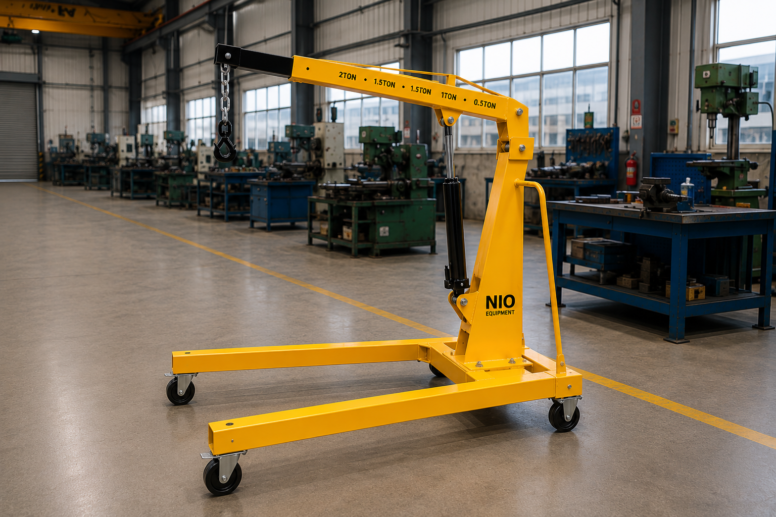
The Nio Equipment Jib Crane is a workstation lifting system for localized material handling, machine servicing, assembly, and production support. Its fabricated steel mast and jib arm provide a rigid lifting path, while the compact operating envelope enables precise load positioning around machines and work cells. Pillar-mounted or wall-mounted arrangements can be configured with suitable boom reach, rotation, hoist type, controls, structural grade, and protective finish to match indoor or outdoor industrial requirements.
Specifications
| Capacity | 250 kg to 5,000 kg |
| Boom Length | 2 m to 6 m |
| Working Radius | Up to 5.5 m |
| Lift Height | Up to 8 m |
| Rotation Angle | 180°, 270° or 360° |
| Mounting Type | Wall mounted or pillar mounted |
| Hoist Type | Manual chain, electric chain or wire rope |
| Slewing Operation | Manual or motorized |
| Power Supply | 230V single-phase or 415V 3-phase, 50 Hz |
Key Features
- Rigid fabricated steel jib structure
- Compact workstation lifting footprint
- Smooth trolley travel along boom
- Accessible components simplify routine maintenance
- Hoist-ready beam supports trolley integration
- Localized circular load coverage
Optional Configurations
- Load Capacity – Rated capacity can be engineered within the available range to suit lifted loads, attachments, operating frequency, and required duty.
- Jib Arm Geometry – Boom length, working radius, and hook travel can be selected around machine clearances, workstation layout, and required load coverage.
- Mounting Arrangement – Choose wall-mounted or pillar-mounted construction according to available building support, floor foundation, operating envelope, and installation constraints.
- Hoist Package – Select manual or electric chain hoists, or a wire rope hoist, to match capacity, lifting speed, and usage frequency.
- Slewing Operation – Manual or motorized slewing can be specified with a suitable rotation angle for positioning accuracy, cycle frequency, and operator effort.
- Control Method – Pendant or wireless remote controls can be configured for electric hoist and slewing functions, improving operator access around bulky loads.
Safety Features
- Overload Protection
- Upper Travel Limit
- Emergency Stop
- Safety Hook Latch
- Slew End Stops
- Electrical Isolation
Certifications & Standards
Use Cases
Product Resources
What Is a Jib Crane?
A Jib Crane is a stationary material handling device with a pivoting arm used for localized lifting and precise positioning of loads within a restricted work cell or workstation environment. It is widely used in industrial settings such as assembly stations, machine maintenance areas, and production lines to facilitate efficient handling and positioning of components and materials.
Working Principle of Jib Crane
The Jib Crane operates on a slewing jib arm mounted either on a wall or pillar, providing rotational movement around a fixed pivot. The lifting mechanism, either manual chain, electric hoist, or wire rope, provides vertical translation lifting and lowering capability. The system enables circular load coverage within a defined radius, allowing precise horizontal positioning by manually or motorized slewing of the jib arm around its pivot point.
Step-by-Step Operation
- Position the lifting hook or hoist over the load.
- Attach load securely to the hoist hook.
- Operate the lifting mechanism to raise the load vertically.
- Swing the jib arm manually or motorized to move the load laterally.
- Lower the load to the desired location precisely.
- Release the load safely by detaching the hook.
- Return jib arm and hoist to loading position for next operation.
Key Components
Safety Features - Detailed
- Overload protection prevents lifting beyond rated capacity
- Upper travel limit stops prevent hoist overtravel
- Emergency stop halts all crane operations immediately
- Safety hook latch secures load attachment
- Slew end stops limit rotational range
- Electrical isolation ensures safe servicing
- Robust mounting prevents structural failure
- Smooth trolley travel reduces sudden load shifts
- Safe working load clearly labeled
- Routine safety inspections recommended
- Controlled rotation reduces swing hazard
- Operator training minimizes misuse risks
- Regular maintenance upholds safety integrity
Selection Factors
- Load capacity requirements
- Boom length and working radius
- Lift height needed
- Mounting type available
- Type of hoist preferred
- Slewing operation mode
- Operating frequency and duty cycle
- Workstation layout constraints
- Power supply availability
- Required rotation angle
- Safety feature needs
- Environmental operating conditions
- Maintenance accessibility
- Load attachment compatibility
- Precision positioning demands
Installation Requirements
- Level and reinforced foundation
- Structural support for wall or pillar
- Adequate clearance for boom rotation
- Electrical power supply connections
- Access for maintenance and inspection
- Secure mounting anchors and bolts
- Coordination with building services
- Operator access and safe working zones
- Commissioning with operational testing
- Clearance for hoist travel
- Load testing prior to use
- Safety signage and barriers
Maintenance Requirements
- Inspect structural integrity regularly
- Lubricate slewing bearings and pivots
- Check hoist chain or wire rope condition
- Test overload protection systems
- Verify operation of emergency stop
- Inspect safety hook latch function
- Examine electrical connections and isolation
- Check trolley wheel condition and alignment
- Look for hydraulic leaks if applicable
- Tighten bolts and mounting fixtures
- Clean components for smooth operation
- Perform functional lifting tests periodically
- Inspect travel limit stops
- Verify control pendant or remote function
Advantages of Jib Crane
- Provides precise localized load positioning
- Requires minimal operating space
- Simpler and faster installation process
- Supports repeatable load placement within radius
- Reduces manual lifting effort
- Improves workstation productivity
- Customizable capacity and boom sizes
- Flexible mounting options available
- Smooth trolley travel for easy load movement
- Compact footprint suits tight work areas
- Enhanced operator safety features integrated
- Enables quick load transfer around workstation
- Supports diverse hoist types
- Low maintenance design components
- Facilitates ergonomic material handling
Limitations of Jib Crane
- Fixed installation location limits mobility
- Limited working radius compared to gantry cranes
- Requires structural support for mounting
- Not suitable for heavy-duty overhead lifting
- Limited vertical travel compared to overhead cranes
- Manual slewing can increase operator effort
- Electric slewing adds installation complexity
- Capacity constrained to 5,000 kg maximum
- Installation requires suitable floor or wall strength
- Not ideal for large area coverage
- Power supply dependency for electric hoists
- Periodic maintenance essential for safe operation
Common Alternatives to Jib Crane
Industry Applications
- Assembly Line Component Lifting
- Motor and Gearbox Positioning
- Fixture Transfer for Machining
- Tooling Changeover Handling
- Production Support Material Movement
- Die and Mold Handling
- Improves assembly line flow
- Enhances load positioning accuracy
- Reduces manual load handling
- Supports efficient tool changeovers
- Minimizes production interruptions
- Facilitates organized workstation lifting
- Machined Component Positioning
- Fabricated Part Handling
- Fixture Transfer Between Workstations
- Assembly Cell Material Feeding
- Production Material Movement
- Tool and Equipment Installation
- Supports controlled material flow
- Reduces handling interruptions
- Improves coordination between work areas
- Enhances workstation productivity
- Minimizes manual lifting effort
- Facilitates precise load positioning
- Loading and Unloading Goods
- Material Transfer Between Floors
- Order Preparation Handling
- Storage Level Stock Movement
- Packaging Material Positioning
- Dispatch Area Loading
- Supports organized inventory movement
- Reduces manual handling between levels
- Improves loading efficiency
- Facilitates safer goods transfer
- Enhances operational flow
- Minimizes handling delays
- Carton and Crate Handling
- Packaging Material Transfer
- Production Line Material Feeding
- Finished Goods Movement
- Storage Area Stock Positioning
- Dispatch Material Loading
- Supports smooth material flow
- Improves coordination between levels
- Reduces manual load handling
- Enhances packaging line support
- Minimizes handling interruptions
- Facilitates efficient goods transfer
- Packaged Product Movement
- Secondary Packaging Handling
- Carton Transfer Between Areas
- Production Support Material Handling
- Storage Material Positioning
- Dispatch Carton Loading
- Supports controlled material movement
- Improves operational area coordination
- Reduces manual handling effort
- Enhances load positioning accuracy
- Facilitates organized stock transfer
- Minimizes material handling interruptions
- Receiving Area Load Transfer
- Storage Level Material Movement
- Dispatch Area Loading
- Operational Floor Material Handling
- Staging Area Stock Positioning
- Pallet Transfer Between Floors
- Supports continuous goods flow
- Improves coordination between levels
- Reduces manual transfer effort
- Enhances load positioning control
- Minimizes handling delays
- Facilitates efficient stock movement
- Raw Material Transfer
- Component and Assembly Handling
- Work-in-Progress Movement
- Finished Goods Positioning
- Production Support Material Handling
- Equipment Installation Support
- Supports organized material flow
- Reduces handling interruptions
- Improves coordination between lines
- Facilitates precise load placement
- Minimizes manual lifting effort
- Enhances production area efficiency
Applications
Industries Served
Customization Options
How Jib Crane Compares to Alternatives
| Alternative | Key Difference |
|---|---|
| Floor Crane | Floor cranes offer mobility within a workspace, unlike fixed jib cranes. |
| Wall Mounted Jib Crane | Wall mounted jib cranes attach to building walls, reducing floor space usage compared to pillar mounted jib cranes. |
| Pillar Mounted Jib Crane | Pillar mounted jib cranes are freestanding and suitable where wall mounting is not feasible. |
| Gantry Crane | Gantry cranes cover larger horizontal areas and are suitable for heavier loads than jib cranes. |
| Hydraulic Floor Crane | Hydraulic floor cranes provide adjustable lifting height and increased flexibility compared to jib cranes. |
| Mobile Floor Crane | Mobile floor cranes allow for lifting in multiple locations with no fixed installation unlike the fixed jib crane. |
| Overhead Bridge Crane | Overhead bridge cranes provide extensive vertical and horizontal travel for heavy-duty lifting beyond jib crane capacity. |
| Industrial Forklift | Industrial forklifts enable load transport and lifting but lack precise localized positioning offered by jib cranes. |
✓ When to Choose Jib Crane
- When precise localized load positioning is needed within a limited working radius at a fixed workstation
- For assembly stations or machine maintenance areas requiring repetitive lifting and positioning tasks
- When floor space is constrained but a stable mounting surface is available on wall or pillar
- If lifting capacities between 250 kg and 5,000 kg suit the load requirements without extensive vertical travel
- When the operating environment benefits from a compact and ergonomic material handling footprint
- For workflows requiring smooth trolley travel and relatively frequent slewing angles of 180°, 270°, or 360°
⚠ When Not to Choose Jib Crane
- If the application demands lifting capacities exceeding 5,000 kg, consider gantry or overhead bridge cranes
- Where wide area coverage and mobility across multiple workstations are required, mobile floor cranes may be preferable
- When vertical lift height exceeds 8 meters or involves significant overhead travel, overhead cranes are better suited
- If floor or wall structural support is insufficient to bear the jib crane load, floor cranes or mobile cranes may be used
- For operations requiring high-frequency slewing with minimal operator effort, fully motorized slewing on other cranes might be required
- When very flexible load transport with multi-directional movement is needed, industrial forklifts or hydraulic floor cranes may offer advantages
Ideal Applications for Jib Crane
Who Uses This Product?
Request a Custom Quote - What We Need to Know
- What is the maximum load capacity required for the jib crane?
- What are the dimensions and approximate weight distribution of the loads to be lifted?
- What is the required boom length and working radius for the application?
- What is the maximum lift height needed for your operations?
- Do you require a wall-mounted or pillar-mounted jib crane installation?
- What type of hoist do you prefer: manual chain, electric chain, or wire rope?
- What is the expected operating frequency or duty cycle of the jib crane?
- What rotation angle is needed for slewing: 180°, 270°, or 360°?
- What power supply is available at the installation site: 230V single-phase or 415V 3-phase?
- Are there any space constraints or specific workstation layout considerations impacting crane installation?
Upgrade Options
Frequently Asked Questions
Why Choose NIO Equipment for Jib Crane
Trusted by manufacturers, warehouses and industrial facilities across India for quality, reliability and after-sales excellence.
- ✓Application-specific lifting engineering
- ✓In-house structural manufacturing capability
- ✓Site survey and layout support
- ✓Flexible control integration expertise
- ✓Coordinated installation project support
- ✓Dedicated after-sales service commitment
About This Product
A Jib Crane is a fixed industrial lifting system designed to raise, move, and accurately position loads within a defined workstation or work-cell radius. It combines a fabricated steel jib arm with a trolley and hoist, allowing vertical lifting, travel along the boom, and rotational movement around a fixed pivot. This localized operating envelope makes the crane suitable for repetitive handling near machines, assembly fixtures, maintenance bays, and production stations.
Localized Material Handling
Unlike an overhead bridge crane that serves a wide building area, a jib crane concentrates lifting capability where materials are repeatedly picked, positioned, or removed. Its compact footprint can reduce dependence on forklifts or general-purpose cranes for routine workstation transfers. The equipment is particularly relevant when a load must be placed accurately rather than simply transported across a facility.
Operating Principle
The load is lifted by a manual chain hoist, electric chain hoist, or wire rope hoist suspended from a trolley on the jib arm. The trolley moves along the boom to vary the hook position, while the arm slews around its wall-mounted or pillar-mounted pivot to provide circular or sector-shaped coverage. Depending on the selected arrangement, slewing may be manual or motorized, with rotation configured for 180°, 270°, or 360°.
Industrial Work Environments
The Jib Crane is primarily intended for indoor industrial environments with a stable mounting structure, suitable operating clearances, and controlled exposure to corrosive conditions. Typical locations include machine shops, fabrication bays, assembly lines, maintenance departments, warehouses, and equipment manufacturing plants. Capacities from 250 kg to 5,000 kg, boom lengths from 2 m to 6 m, and lift heights up to 8 m support a broad range of localized handling duties.
Selection Context
A jib crane is most appropriate when loads remain within a fixed operating radius and the workflow benefits from repeatable lifting at a specific station. It is not intended to replace a gantry or overhead bridge crane where extensive building coverage, capacity above 5,000 kg, or greater vertical travel is required. Selection should therefore consider the load, attachment weight, duty, hook travel, rotation envelope, supporting structure, and interaction with surrounding equipment.
Applications
Machine Maintenance Tasks
During machine tool servicing, the crane can lift motors, gearboxes, pumps, compressors, and other removable assemblies from their installed positions. Trolley travel and jib rotation allow the component to be moved clear of the machine and lowered onto a service stand or transport device. This avoids using manual lifting methods in congested maintenance areas and gives technicians better control during removal and reinstallation.
Component Assembly Cells
At an assembly station, a Jib Crane can pick components from a nearby rack, pallet, fixture, or material cart and position them over the assembly point. Controlled vertical movement helps align mating parts without requiring operators to support the full load. Pendant or wireless remote control may be configured for electric hoist and motorized slewing functions when access around a large component is restricted.
Production Line Support
The crane can feed work-in-progress components to a production line or remove completed assemblies from a workstation. Its fixed coverage area encourages a defined pickup and placement sequence, which can improve coordination between operators, machines, and material carts. Capacity, boom geometry, and hook travel should be matched to the line layout and the heaviest combined load, including any lifting attachment.
Tooling And Fixture Changes
Dies, molds, machining fixtures, welding fixtures, and production tooling often require careful positioning during changeovers. A jib crane allows the tooling to be raised, moved along the boom, and slewed into alignment with the machine or storage stand. This supports controlled changeovers while reducing the need to bring a forklift into the immediate operating area.
Welding Shop Transfers
Fabricated parts and weldments can be transferred between a welding table, positioner, inspection point, and nearby staging location when all points lie within the crane radius. The rigid steel jib structure and smooth trolley movement support deliberate placement of irregular components. Suitable rigging remains essential because fabricated loads may have offset centers of gravity or unstable lifting orientations.
Equipment Installation Work
A Jib Crane can support installation and replacement of plant equipment where controlled lifting is required near a fixed machine or process unit. Typical tasks include positioning drives, production tools, structural parts, and serviceable equipment modules. Unusual load shapes, restricted clearances, or non-standard hook travel should be reviewed through project-specific engineering before the crane arrangement is finalized.
Warehouse Handling Points
In warehouse and dispatch areas, the crane can assist with loading or unloading crates, packaged goods, storage containers, and suitably rigged palletized loads at a defined handling point. It is useful where goods must be transferred between a vehicle, staging surface, or storage position within the available lifting radius. It does not provide the facility-wide mobility of a forklift or mobile crane, so the surrounding material-flow plan must account for onward transport.
Workstation Material Feeding
Raw materials, machined components, packaging supplies, and finished products can be moved into or out of an industrial work cell without occupying the entire area with mobile lifting equipment. The crane can be arranged to serve repeatable pickup and landing positions around its pivot. This application is especially effective when load weights, attachment methods, and workstation geometry are consistent and clearly defined.
Benefits
Reduced Manual Handling
By providing mechanical lifting directly at the point of use, the Jib Crane reduces the need for operators to raise or support heavy components manually. The hoist carries the vertical load while the trolley and slewing arm guide it through the workstation. This can improve ergonomics and help reduce handling effort during repetitive assembly, maintenance, and tooling operations.
Precise Load Placement
Vertical hoist control, trolley travel, and jib rotation provide three coordinated movements for localized positioning. Operators can align motors, fixtures, weldments, and assemblies with machines or receiving surfaces more accurately than with uncontrolled manual transfer. Motorized slewing and electric hoist controls may be selected where cycle frequency or positioning demands make manual operation less suitable.
Efficient Space Use
A wall-mounted arrangement can preserve floor area by using a suitable building structure, while a pillar-mounted crane creates an independent lifting point where wall support is unavailable. Both arrangements concentrate coverage around a defined workstation rather than requiring a large travelling-crane structure. The selected rotation angle and boom length can be matched to the usable area while avoiding unnecessary interference with aisles and adjacent equipment.
Improved Workflow Continuity
Dedicated lifting at a machine or assembly cell reduces waiting for shared forklifts, mobile cranes, or building-wide lifting equipment during routine transfers. Loads can remain within an organized sequence from staging to processing and onward placement. This supports workstation productivity and throughput without implying that the crane itself transports goods beyond its fixed operating radius.
Application Configuration Flexibility
The crane may be engineered with an appropriate capacity, jib geometry, mounting arrangement, hoist package, slewing method, and control system. This allows the equipment to be aligned with load characteristics, operating frequency, power availability, and operator access. A correctly selected configuration can lower unnecessary complexity and maintenance overhead while retaining the functions required by the application.
Technical Highlights
Fabricated Jib Structure
The load-supporting assembly uses a rigid fabricated steel jib arm designed to carry the hoist and trolley within the rated operating envelope. Boom support brackets, mounting interfaces, and the pivot arrangement transfer vertical loads and overturning moments into the wall structure or pillar foundation. Structural configuration must therefore be coordinated with the selected capacity, boom length, and mounting condition.
Capacity And Reach
Available load capacity ranges from 250 kg to 5,000 kg, with boom lengths from 2 m to 6 m and a working radius up to 5.5 m. Lift height can be configured up to 8 m, subject to the installation geometry and selected hoist. The final rated capacity must account for the lifted item, below-hook attachment, expected operating frequency, and relevant duty requirements.
Hoist And Trolley Options
The hoist-ready beam supports trolley integration for manual chain, electric chain, or wire rope hoists. Manual chain hoists are suited to applications where lifting is less frequent and electrical operation is unnecessary, while electric chain or wire rope arrangements can support higher operating convenience and application-specific lifting requirements. Trolley wheels and alignment are arranged to provide smooth travel along the boom and controlled changes in hook position.
Slewing Configuration
The arm rotates around a fixed pivot using manual or motorized slewing, depending on operator effort, load control, and cycle frequency requirements. Rotation may be arranged for 180°, 270°, or 360°, with the appropriate operating envelope established during layout planning. Slew end stops limit travel where a restricted rotational range is selected and help prevent movement into designated obstructions or exclusion areas.
Electrical And Controls
Electric configurations can be designed for a 230V single-phase or 415V three-phase, 50 Hz power supply. Pendant controls may place hoist and slewing commands at the operator position, while wireless remote control can be configured where mobility around bulky loads is beneficial. Electrical isolation and emergency stopping provisions support controlled shutdown and safer servicing of powered functions.
Integrated Safety Functions
Product safety provisions include overload protection, an upper travel limit, an emergency stop, a safety hook latch, slew end stops, and electrical isolation. Overload protection restricts lifting beyond the rated capacity, while the upper limit helps prevent hoist overtravel. The hook latch assists with load retention, although it does not replace correct sling selection, secure rigging, or pre-lift inspection.
Maintainable Component Layout
Accessible mechanical and electrical components simplify routine inspection, adjustment, and service work. Maintenance personnel can examine the hoist medium, trolley wheels, pivot points, slew bearing, fasteners, controls, and safety devices without treating the crane as a sealed assembly. Actual access requirements should be included in the installation layout so inspections can be performed without entering an unsafe load path.
Industries Served
Automotive Manufacturing
Automotive plants use localized lifting for engines, gearbox assemblies, production fixtures, tooling, dies, and line-side components. A Jib Crane can serve assembly cells, maintenance stations, machining operations, and tooling-change locations where repeatable movement occurs around a fixed point. Boom reach, rotation, and controls can be selected to fit around conveyors, machines, fixtures, and operator work zones.
General Engineering
General engineering facilities handle machined parts, fabricated assemblies, structural components, tools, and work-in-progress goods with varied shapes and lifting points. The crane can transfer these loads between a machine, inspection table, fixture, and local staging area. Application-specific rigging and hoist selection are important where component geometry or handling frequency changes between jobs.
Metal Fabrication
Fabrication shops often need to move weldments, plate-based assemblies, jigs, and fixtures around welding or fitting stations. The rotating arm provides localized access without requiring mobile equipment to enter every work bay. For long, irregular, or offset loads, the working radius and center of gravity must be evaluated so that the load remains controllable throughout the lift.
Machine Tool Manufacturing
Machine tool builders and users require accurate handling of motors, gearboxes, fixtures, tooling, and machine subassemblies during assembly and service. A pillar-mounted or wall-mounted Jib Crane can be positioned beside the machine to support installation, adjustment, and replacement work. Precise hook access and adequate maintenance clearance are more important in this setting than broad facility coverage.
Warehousing And Logistics
Warehouse, receiving, staging, and dispatch operations may use the crane to handle crates, containers, packaged shipments, loading carts, or appropriately rigged palletized goods. The equipment is best applied at a fixed loading point where vertical lifting and short-radius positioning are required. Forklifts or other transport equipment remain necessary when goods must travel beyond the jib crane's operating envelope.
Process Equipment Manufacturing
Manufacturers of pumps, compressors, vessels, and related process equipment handle dense components that require controlled alignment during assembly and testing. The crane can position drive units, casings, service components, and fabricated modules within a dedicated work cell. Motorized slewing or remote control may be configured where load size limits direct operator access.
Industrial Maintenance Operations
Maintenance departments can use the crane at repair bays or beside fixed plant equipment to remove and reinstall serviceable components. This supports motor replacement, pump and compressor maintenance, equipment installation, and tooling changes without repeatedly arranging a general-purpose crane. The mounting location should be selected around likely service paths so the hook can reach both the equipment and a safe landing position.
Packaging And Consumer Goods
FMCG and pharmaceutical operations may apply a jib crane to secondary packaging, carton, crate, container, or production-support material handling where load and environmental requirements are suitable. It can move materials between a defined storage, staging, packaging, or dispatch position within its lifting radius. The exact construction, lifting attachment, and operating controls should be evaluated against site-specific cleanliness, product protection, and workflow needs.
Why Choose NIO Equipment
Application-Specific Engineering
Nio Equipment evaluates the Jib Crane around the actual load, workstation, operating radius, lift height, duty, and material-flow requirement. This helps engineering and procurement teams avoid selecting a crane solely from nominal capacity. Complex centers of gravity, unusual boom geometry, high operating frequency, or lift requirements beyond the stated range can be identified early for further evaluation or an alternative crane solution.
Configurable Crane Design
The crane can be configured with wall or pillar mounting, manual or powered hoisting, manual or motorized slewing, and pendant or wireless controls. Nio Equipment can also tailor capacity, boom length, working radius, and hook travel within the supported product range. These choices allow the crane to be aligned with operator access, machine clearance, power availability, and the frequency of lifting.
Manufacturing And Integration
Nio Equipment combines in-house structural manufacturing capability with experience in material handling equipment and industrial lifting systems. Site survey and layout support can connect the fabricated jib structure, mounting arrangement, hoist package, and controls to the surrounding facility. This integration focus is valuable where crane movement must coexist with machines, aisles, building services, and established production workflows.
Project Coordination Support
Installation and commissioning support can help coordinate foundations, wall supports, electrical provisions, operational clearances, testing, and operator handover. Nio Equipment also provides after-sales support for customers across India. The coordinated approach gives plant teams a defined path from application review and configuration through installation planning and ongoing equipment support.
RFQ Engineering Guidance
For an accurate quotation, buyers can provide the load and attachment weight, required capacity, boom length, working radius, lift height, mounting preference, rotation angle, hoist type, power supply, and preferred controls. Details of duty, load shape, pickup and landing points, structural constraints, and surrounding obstructions further improve configuration accuracy. Nio Equipment can use this information to identify standard-range requirements, customization needs, and situations where another industrial crane type should be considered.
Installation Guide
Site And Workflow Survey
Installation planning should begin with a survey of pickup points, landing positions, machine clearances, aisles, building services, and operator access. The required boom sweep must be checked through its full selected rotation angle, including the space occupied by the load and rigging. This survey also determines whether a wall-mounted or pillar-mounted arrangement best supports the intended material flow.
Load Path Assessment
The planned load path should remain clear of machines, columns, cable trays, lighting, pipework, storage racks, and pedestrian routes. Hook travel and lift height must allow the load to clear intervening equipment without creating excessive suspension height or uncontrolled swing. Where complex load shapes or offset centers of gravity are involved, the rigging method and crane geometry require additional engineering review.
Pillar Foundation Requirements
A pillar-mounted Jib Crane requires a level, reinforced foundation capable of carrying crane reactions generated during lifting, trolley travel, and slewing. Mounting anchors and bolts must be selected and installed for the engineered column and foundation arrangement. Foundation dimensions and reinforcement are project-specific and should not be assumed from crane capacity alone because boom reach and site conditions also influence loading.
Wall Support Assessment
A wall-mounted crane transfers vertical forces and significant moment loads into the supporting building structure. The wall, columns, brackets, and connection points must be evaluated for the selected capacity and jib geometry, with reinforcement provided where required. Wall mounting should not proceed solely because a visually convenient surface is available; structural suitability must be established before fabrication and installation.
Electrical Service Planning
Electric hoists and motorized slewing systems require a suitable 230V single-phase or 415V three-phase, 50 Hz supply according to the selected equipment. Installation planning should include cable routing, protective devices, accessible isolation, control connections, and movement allowances for rotating components. Electrical work must be coordinated with the site safety system and kept clear of the trolley path and mechanical pinch points.
Clearance And Access
Adequate clearance is required for boom rotation, trolley movement, hook travel, load handling, inspection, and emergency intervention. Safe working zones, signage, and barriers should be arranged according to the surrounding traffic and operational risks. Maintenance access to the hoist, pivot, trolley, controls, anchors, and isolation point should remain available after nearby machines or storage systems are installed.
Commissioning And Testing
After erection, mounting bolts, structural connections, trolley alignment, rotational limits, electrical functions, and control directions should be verified. Commissioning should include operational testing, safety-device checks, and load testing using appropriate procedures before the crane enters service. Operator handover should cover rated capacity, operating envelope, control functions, emergency response, inspection points, and restrictions specific to the installed configuration.
Maintenance Guide
Routine Visual Checks
Routine inspection should identify deformation, cracking, corrosion, damaged labels, loose hardware, unusual trolley alignment, and changes in the crane's rotational movement. Operators should also look for abnormal noise, vibration, binding, or sudden movement before and during use. Any condition that may affect structural integrity or load control should be reported and assessed before further lifting.
Hoist And Hook Inspection
The manual chain, electric chain, or wire rope should be examined for wear, deformation, damaged links, broken wires, poor reeving, and other deterioration relevant to the selected hoist. The load hook and safety latch must move correctly and show no visible distortion or damage. Hoist braking, lifting, lowering, and upper-limit operation should be checked periodically according to operating conditions and equipment documentation.
Trolley And Slew Care
Trolley wheels, bearings, pivots, and the slew bearing should be kept clean, correctly aligned, and lubricated at the specified service points. Excessive wheel wear or poor alignment can increase travel resistance and produce irregular load movement. Slew end stops and rotational components should also be inspected for looseness, impact damage, and smooth operation.
Structure And Fasteners
The jib arm, supporting brackets, pillar, wall connections, anchors, and mounting bolts require periodic examination for movement, fatigue indicators, corrosion, or loss of tightness. Particular attention should be given to connection areas that transfer load into the foundation or building structure. Structural repairs or modifications should be evaluated by qualified personnel rather than performed as unapproved field alterations.
Controls And Safety Devices
Powered cranes require inspection of electrical cables, pendant or remote controls, connectors, isolation equipment, and protective enclosures. Emergency stops, overload protection, upper travel limits, and other fitted control devices should be functionally verified at appropriate intervals. Damaged controls or intermittent electrical behavior should be corrected before the equipment is returned to normal operation.
Maintenance Records
Inspection findings, repairs, component replacements, functional tests, and load-test results should be documented to support equipment history and maintenance planning. Service frequency should reflect usage, load severity, environmental conditions, and recommendations in the supplied documentation rather than an assumed universal interval. Consistent records help maintenance teams identify recurring wear and plan intervention before reliability is affected.
Safety Guide
Trained Operator Control
Only trained personnel should operate the Jib Crane or attach loads to its hook. Operators must understand the rated capacity, control functions, rotation limits, load path, emergency stop, and local exclusion arrangements. The crane is intended for material handling and must not be used to lift or transport personnel.
Rated Load Compliance
The combined weight of the load, slings, lifting beams, grabs, and other below-hook devices must remain within the crane's rated capacity. Overload protection provides an important safeguard but must not be used as a weighing method or substitute for load verification. Unknown loads, unusual centers of gravity, or loads approaching the application limit should be reviewed before lifting.
Secure Load Attachment
Loads should be attached with compatible, inspected rigging and positioned so that lifting begins without uncontrolled tilting or slipping. The safety hook latch must close correctly, and side loading of the hook or dragging of loads should be avoided. A preliminary controlled lift can be used to confirm balance and attachment security before slewing or trolley movement.
Controlled Load Movement
Personnel should remain clear of suspended loads, pinch points, and the rotating jib arm. Lifting, trolley travel, and slewing should be performed smoothly to limit load swing and sudden forces on the structure. Operators must confirm that the full route is clear before movement and should never use the load to push equipment or people from the travel path.
Pre-Operation Safety Checks
Before use, the operator should check the hook latch, hoist chain or wire rope, controls, emergency stop, travel limits, visible structure, and surrounding clearances. Slew end stops and the upper travel limit should remain functional for the installed configuration. If a defect affects safe operation, the crane should be isolated and referred for inspection rather than used until failure occurs.
Safe Maintenance Isolation
Maintenance must be performed with the load removed and powered functions electrically isolated against unintended operation. Stored or suspended load hazards should be eliminated before personnel work on the hoist, trolley, pivot, or mounting system. Unauthorized changes to capacity, boom geometry, hoist equipment, controls, stops, or structural connections can alter crane reactions and must not be made without engineering evaluation.