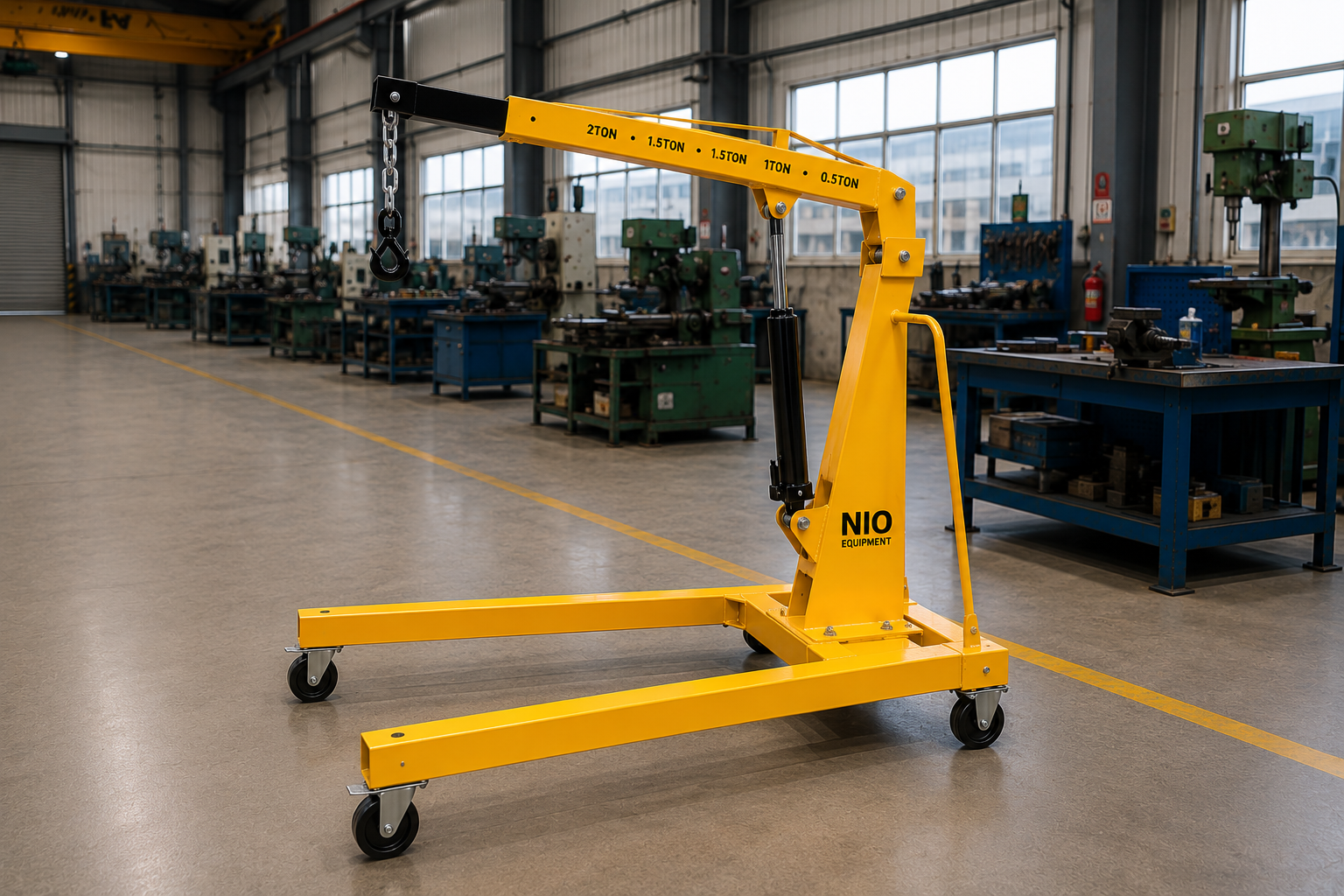
The Nio Equipment Pillar Mounted Jib Crane is a freestanding workstation crane for localized lifting, transfer, and precise positioning of industrial loads. Its rigid floor-mounted pillar and fabricated steel jib provide stable support without relying on a building wall, while the rotating arm serves machines, assembly stations, and maintenance areas. Capacity, arm length, lift height, hoist type, slewing arrangement, mounting design, and protective finish can be customized to suit the site and handling duty.
Specifications
| Rated Capacity | 250 kg to 5,000 kg |
| Jib Arm Length | 2 m to 8 m |
| Lift Height | 2 m to 6 m |
| Rotation Angle | Up to 360° |
| Hoist Type | Manual chain hoist, electric chain hoist, wire rope hoist |
| Slewing Operation | Manual or motorized |
| Power Supply | 415 V, 3-phase, 50 Hz for electric configurations |
| Mounting Arrangement | Floor-mounted pillar with anchor-bolt foundation |
| Structure | Fabricated structural steel pillar and jib arm |
Key Features
- Freestanding pillar supports localized lifting coverage
- Rigid fabricated steel column and jib arm
- Smooth slewing enables controlled load movement
- Compact footprint preserves surrounding floor access
- Independent structure avoids building wall loading
- Hoist-ready beam supports horizontal trolley travel
- Accessible components simplify routine maintenance
Optional Configurations
- Load Capacity – Rated capacity can be selected according to maximum load weight, lifting frequency, attachment weight, and required industrial duty.
- Jib Arm Geometry – Arm length, working radius, hook height, and rotation coverage can be adapted to the workstation layout and handling envelope.
- Hoist Selection – Manual chain, electric chain, or wire rope hoists can be specified according to load, frequency, and positioning requirements.
- Slewing Operation – Manual or motorized slewing can be selected to suit load weight, operating frequency, travel control, and positioning accuracy.
- Foundation Arrangement – Base plate, anchor bolt, and foundation details can be engineered around floor construction and calculated crane reactions.
- Protective Finish – Paint system, corrosion protection, and industrial color can be selected for indoor, outdoor, or application-specific operating environments.
Safety Features
- Overload Protection
- Emergency Stop
- Upper Limit Switch
- Lower Limit Switch
- Hook Safety Latch
- Slew End Stops
- Electrical Phase Protection
Certifications & Standards
Use Cases
Product Resources
What Is a Pillar Mounted Jib Crane?
The Pillar Mounted Jib Crane is a freestanding industrial crane designed for precise localized lifting and horizontal load positioning. It is typically installed on a floor-mounted pillar to serve workstations, assembly lines, and maintenance areas. This crane supports material handling that requires independent structural support without relying on building walls.
Working Principle of Pillar Mounted Jib Crane
This crane operates on a mechanical lifting principle supported by a rigid pillar and fabricates steel jib arm. The load is lifted vertically via a hoist (manual or electric) attached to a horizontal trolley which moves along the arm. The jib arm rotates up to 360° around the pillar, allowing flexible workstation coverage and precise load positioning without wall support.
Step-by-Step Operation
- Position the load beneath the hoist hook on the jib arm.
- Attach the load securely using the safety latch hook.
- Operate the hoist mechanism to lift the load vertically.
- Slew the jib arm manually or motorized to position load horizontally.
- Traverse the hoist trolley along the beam as needed.
- Lower the load precisely at the target location.
- Detach the load and return hoist and jib to rest position.
Key Components
Safety Features - Detailed
- Overload protection to prevent excess lifting
- Emergency stop immediately disables operations
- Upper limit switch stops upward travel
- Lower limit switch stops downward travel
- Hook safety latch prevents load drops
- Slew end stops limit arm rotation range
- Electrical phase protection guards motor circuits
- Manual operation reduces electrical accident risks
- Robust structural design minimizes collapse risk
- Visible safety labels on operating controls
- Routine inspection protocols recommended
- Operator training essential for safe handling
- Clear working area avoids collision hazards
- Anchored base plate prevents crane tipping
- Compliant with industrial lifting safety standards
Selection Factors
- Load capacity requirements
- Jib arm length and geometry
- Lift height needed
- Rotation angle requirements
- Type of hoist selection
- Slewing operation preference
- Available installation space
- Floor structural capacity
- Frequency of use
- Required horizontal trolley travel
- Power supply availability
- Safety and compliance needs
- Environmental operating conditions
- Customization and finish options
Installation Requirements
- Level and reinforced foundation
- Anchor bolt provision for base plate
- Adequate overhead and radial clearance
- Electrical three-phase supply access
- Proper alignment of pillar and jib arm
- Secure hoist and trolley mounting
- Safe access for operator
- Load testing compliance before commissioning
- Provision for emergency stop integration
- Coordination with floor structural engineers
Maintenance Requirements
- Lubrication of slew bearing and joints
- Inspection of hoist chain or wire rope
- Safety latch and hook checks
- Verification of limit switch function
- Structural integrity inspections
- Fastener torque inspections
- Electrical phase protection testing
- Emergency stop function tests
- Inspection for corrosion and paint damage
- Operational check of slewing motion
- Inspection for wear on trolley wheels
- Hydraulic component check if applicable
- Routine cleaning of critical parts
Advantages of Pillar Mounted Jib Crane
- Provides independent freestanding support
- Enables 360° rotational coverage
- Allows precise horizontal load positioning
- Reduces reliance on building structures
- Accommodates multiple hoist types
- Compact floor footprint
- Improves operator ergonomics
- Supports heavy industrial loads
- Simplifies maintenance access
- Customizable arm length and capacity
- Suitable for varied industrial applications
- Increases material handling productivity
- Enhances workplace safety compliance
- Reduces operator fatigue
- Facilitates flexible workstation layouts
Limitations of Pillar Mounted Jib Crane
- Requires substantial floor foundation
- Fixed installation location
- Limited vertical lift height range
- Not suitable for mobile operations
- Limited by pillar placement constraints
- Electrical power needed for motorized slewing
- Load capacity limited to 5,000 kg max
- Requires clear overhead and radial space
- Periodic safety feature inspections mandatory
- Not suited for uneven or unstable floors
Common Alternatives to Pillar Mounted Jib Crane
Industry Applications
- Assembly Line Component Transfer
- Motor And Gearbox Positioning
- Die And Mold Handling
- Machine Maintenance Lifting
- Tooling And Fixture Movement
- Production Support Material Transfer
- Improves assembly throughput
- Reduces operator fatigue
- Supports flexible workflow layouts
- Enhances load positioning accuracy
- Shortens component transfer cycles
- Lowers manual lifting risks
- Fabricated Part Lifting
- Machined Component Handling
- Workstation Component Positioning
- Tool Room Material Transfer
- Equipment Installation Assistance
- Assembly Fixture Movement
- Supports organized material flow
- Reduces handling interruptions
- Improves work area coordination
- Lowers manual handling fatigue
- Enhances load control precision
- Simplifies maintenance lifting operations
- Inventory Transfer Between Levels
- Mezzanine Stock Handling
- Receiving Area Material Transfer
- Dispatch Floor Loading
- Order Preparation Lifting
- Storage Area Component Movement
- Supports vertical inventory movement
- Reduces manual handling between floors
- Improves goods transfer continuity
- Enhances operational floor access
- Minimizes load handling interruptions
- Simplifies load positioning accuracy
- Carton Transfer Between Stations
- Packaging Material Handling
- Production Support Material Movement
- Crate Positioning For Packing
- Finished Goods Lifting
- Loading Area Material Transfer
- Enhances material flow
- Reduces manual handling fatigue
- Supports coordinated packing processes
- Improves load positioning control
- Shortens material transfer times
- Maintains floor space accessibility
- Carton Movement Between Floors
- Secondary Packaging Transfer
- Production Support Material Handling
- Container Lifting At Workstations
- Packaged Product Positioning
- Material Transfer For Maintenance
- Supports controlled material flow
- Reduces manual lifting demands
- Improves load handling safety
- Enhances workspace material transfer
- Facilitates organized operational flow
- Minimizes handling interruptions
- Receiving Area Load Transfer
- Storage Level Material Handling
- Dispatch Area Positioning
- Operational Floor Material Movement
- Staging Area Load Lifting
- Package Transfer Between Stations
- Improves goods movement continuity
- Supports operational level coordination
- Reduces unnecessary manual handling
- Enhances load positioning control
- Maintains workflow flexibility
- Minimizes handling delays
- Raw Material Lifting
- Component Transfer Between Lines
- Work-in-Progress Material Handling
- Finished Goods Positioning
- Production Support Material Movement
- Tooling And Fixture Lifting
- Supports organized material flow
- Reduces manual handling effort
- Improves production line coordination
- Lowers operator fatigue
- Enhances load positioning accuracy
- Shortens material transfer times
Applications
Industries Served
Customization Options
How Pillar Mounted Jib Crane Compares to Alternatives
| Alternative | Key Difference |
|---|---|
| Floor Crane | Floor cranes offer mobile lifting without fixed installation but lack the compact localized coverage of pillar mounted jib cranes. |
| Hydraulic Floor Crane | Hydraulic floor cranes provide mobile lifting with adjustable height and lift capacity, differing from the fixed, slewing jib arm support of pillar mounted cranes. |
| Mobile Floor Crane | Mobile floor cranes allow flexible movement around the facility unlike the fixed position of pillar mounted jib cranes optimized for localized lifting. |
| Wall Mounted Jib Crane | Wall mounted jib cranes depend on building structures for support, whereas pillar mounted jib cranes are freestanding and independent of wall loading. |
| Standard Jib Crane | Standard jib cranes encompass both pillar and wall mounted types, while pillar mounted jib cranes specifically provide a floor-standing support with 360° rotation. |
| Gantry Crane | Gantry cranes span larger floor areas and offer overhead lifting across wider zones, contrasting the more compact, fixed radius of pillar mounted jib cranes. |
| Industrial Forklift | Industrial forklifts provide mobile horizontal and vertical material transport suited for bulk loads, unlike the stationary, precise positioning focus of pillar mounted jib cranes. |
| Electric Hoist System | Electric hoist systems can be overhead or portable and provide vertical lifting but typically lack the dedicated slewing and arm radius control of pillar jib cranes. |
✓ When to Choose Pillar Mounted Jib Crane
- When lifting loads between 250 kg and 5,000 kg in a fixed workstation requiring frequent maneuvering around machines or assembly stations.
- If precise horizontal load positioning with up to 360-degree rotation is needed within a confined floor area.
- When installation environment allows for a robust floor foundation to support a freestanding pillar structure without relying on building walls.
- Where operator ergonomics and reduction of manual labor are priorities to increase throughput and shorten transfer cycles.
- When customization is needed for jib arm length, hoist type, and slewing operation to fit a specific industrial workflow or tooling transfer process.
- If frequent material handling around machine maintenance or tool room operations requires localized, flexible lifting coverage with minimal floor space impact.
⚠ When Not to Choose Pillar Mounted Jib Crane
- If the lifting application requires a mobile solution adaptable to multiple locations across a facility, consider mobile floor cranes instead.
- When vertical lift heights exceed the 6-meter maximum supported or if overhead clearance is highly restricted, alternate overhead crane systems might be better suited.
- If the installation area has uneven or unstable floors that cannot support a substantial pillar foundation, other mobile or wall-mounted cranes may be preferable.
- When load capacities above 5,000 kg are needed, evaluating gantry cranes or overhead bridge cranes is advisable.
- If power supply constraints exist or motorized slewing is required but not feasible, manual cranes or simple hoist systems could be more appropriate.
- In cases where installation space cannot accommodate the radial and overhead space required for a pillar mounted jib crane, wall-mounted jib cranes or portable lifting devices should be considered.
Ideal Applications for Pillar Mounted Jib Crane
Who Uses This Product?
Request a Custom Quote - What We Need to Know
- What is the maximum load capacity (kg) required for your lifting application?
- What are the approximate dimensions and weight characteristics of the load to be lifted?
- What jib arm length (m) and working radius are needed for your workstation layout?
- What is the required lift height (m) for your operation?
- Do you require manual chain hoist, electric chain hoist, or wire rope hoist for the lifting mechanism?
- Is slewing operation preferred to be manual or motorized?
- What is the expected frequency of crane use (daily/weekly cycles)?
- What are your available floor space and foundation conditions for installation?
- Are there any special environmental or operational conditions influencing crane design or finish?
- What type of power supply is available for the electric configurations (if applicable)?
Upgrade Options
Frequently Asked Questions
Why Choose NIO Equipment for Pillar Mounted Jib Crane
Trusted by manufacturers, warehouses and industrial facilities across India for quality, reliability and after-sales excellence.
- ✓Application-specific jib crane engineering
- ✓In-house structural fabrication capability
- ✓Custom geometry development capability
- ✓Coordinated mechanical and electrical integration
- ✓Project-focused installation planning assistance
- ✓Responsive after-sales service coordination
About This Product
The Pillar Mounted Jib Crane is a freestanding industrial crane for lifting, transferring, and accurately positioning loads within a defined workstation radius. Its floor-mounted pillar provides independent structural support, making the crane suitable where a building wall cannot carry crane reactions or where unrestricted workstation placement is required. Typical locations include machine tools, assembly stations, fabrication bays, maintenance zones, and tool rooms.
Localized Material Movement
This crane combines vertical hoisting, horizontal trolley travel, and rotational arm movement to cover a localized handling envelope. The hoist raises or lowers the load, the trolley moves it along the jib arm, and manual or motorized slewing positions it around the pillar. This coordinated motion supports controlled transfers between staging points, machines, fixtures, workbenches, and maintenance positions.
Freestanding Operating Principle
A fabricated structural steel pillar is anchored to a suitably engineered floor foundation, while the horizontal jib arm carries the trolley and selected hoist. Depending on the configuration, a manual chain hoist, electric chain hoist, or wire rope hoist provides vertical lifting. The arm can provide rotation of up to 360°, subject to the selected arrangement, site layout, services, and required slew limits.
Workstation Integration
The Pillar Mounted Jib Crane is particularly relevant to repetitive workflows in which a load must be picked up, raised clear of an obstruction, moved through a short horizontal path, and lowered accurately. It can reduce dependence on forklifts or larger overhead cranes for routine workstation handling while preserving access around production equipment. Its compact base footprint also helps organize lifting activity around a predictable load path.
Application And Selection Range
Available engineering parameters include rated capacities from 250 kg to 5,000 kg, jib arm lengths from 2 m to 8 m, and lift heights from 2 m to 6 m. Final selection depends on the maximum lifted load, attachment weight, operating frequency, hook height, working radius, trolley travel, and floor conditions. Indoor or sheltered use is generally preferred, although protective finishes can be selected for project-specific outdoor or corrosive environments.
Applications
Machine Tool Loading
At machining centers, lathes, and similar equipment, the crane can lift workpieces from a nearby trolley or staging point and position them at the machine interface. Horizontal trolley travel and jib rotation allow the operator to approach the loading area without repeatedly moving floor-based handling equipment. Controlled lowering is especially useful when aligning machined components with chucks, fixtures, or supporting surfaces.
Assembly Component Handling
On assembly lines and standalone workstations, a Pillar Mounted Jib Crane can transfer motors, gearboxes, fabricated parts, fixtures, and production tools into assembly position. The crane supports vertical lifting and short-radius movement while the operator guides the load into alignment. Hoist and slewing selection can be matched to the component weight, handling frequency, and positioning accuracy required by the process.
Maintenance And Replacement
Maintenance teams can use the crane to remove and replace motors, pumps, gearboxes, and other machine components located within the jib operating envelope. A fixed lifting point near the equipment reduces the need to arrange a mobile crane for each routine intervention. Adequate hook access, headroom, radial clearance, and a clear removal path must be considered during layout planning.
Die And Mold Positioning
Dies, molds, and production tooling often require controlled movement between storage stands, maintenance benches, and machines. The jib crane can raise these loads, traverse them along the arm, and slew them toward the required position while reducing direct manual lifting. Capacity selection must account for the complete suspended weight, including lifting beams, slings, or other attachments.
Fabrication Shop Transfer
In fabrication and welding areas, the crane can handle fabricated parts, weldments, fixtures, and work-in-progress items between preparation, welding, inspection, and rework positions. Its defined rotational coverage can connect adjacent process points without occupying the travel aisle used by carts or forklifts. Protective finish and component selection should reflect dust, debris, and environmental exposure at the installation site.
Tool Room Operations
Tool rooms frequently handle dense tooling, fixtures, machine accessories, and maintenance equipment that are difficult to position manually. A workstation jib crane provides a permanent lifting resource for movement between storage, inspection, repair, and setup areas. The configuration can be adapted around bench height, required hook height, arm radius, and available overhead clearance.
Pump And Motor Handling
Pump and motor manufacturing workflows require component movement during assembly, testing, maintenance, and final positioning. The crane can lift casings, rotating assemblies, motors, and completed units within its rated capacity and handling radius. Accurate lowering helps place components onto bases, test fixtures, or mating equipment without unnecessary manual force.
Warehouse Staging Support
In receiving, storage, and dispatch zones, the crane may support localized handling of crates, boxes, containers, packaged equipment, and production supplies. It is most appropriate where loads move repeatedly between fixed staging points rather than across an entire warehouse. Palletized or irregular loads require suitable below-hook attachments and must remain within the rated capacity and available handling envelope.
Benefits
Reduced Manual Handling
The hoist carries the vertical load while the trolley and slewing arm support controlled horizontal positioning. This reduces the need for operators to lift, carry, or force heavy components into place by hand. Better mechanical assistance can lower fatigue and support safer, more consistent handling practices.
Faster Workstation Transfers
A permanently located crane can be available at the point where repetitive lifting occurs, avoiding delays associated with requesting shared handling equipment. Loads can move directly between nearby staging, processing, and installation positions. This can shorten transfer cycles and support higher handling throughput without claiming a fixed productivity increase.
Accurate Load Positioning
Vertical hoist control, beam-mounted trolley movement, and rotational coverage provide multiple directions of load adjustment. This is valuable when aligning motors, gearboxes, dies, fixtures, or machined components with equipment interfaces. More controlled positioning can also help limit impact, scraping, and product damage during transfer.
Independent Structural Support
The floor-mounted pillar avoids applying jib crane loads to a building wall. This enables installation in open production areas or near machines where suitable wall support is unavailable. The benefit depends on providing a foundation capable of resisting the calculated vertical, overturning, and anchoring reactions.
Efficient Space Utilization
The crane concentrates lifting coverage around a defined radius while retaining floor access beneath much of the arm. This can reduce congestion from mobile handling devices in tightly organized work areas. Because the installation is fixed, its load path can also be incorporated into workstation layouts, exclusion zones, and material flow planning.
Configurable Workflow Support
Capacity, jib geometry, hoist type, slewing method, foundation arrangement, and protective finish can be selected around the application. This allows engineering teams to balance operator effort, lifting frequency, positioning needs, environmental conditions, and available space. Application-specific configuration helps avoid overspecifying unrelated features while addressing the actual handling task.
Technical Highlights
Fabricated Steel Structure
The load-supporting structure consists of a fabricated structural steel pillar and jib arm. The rigid column transfers crane reactions through the base plate and anchor bolts into the engineered foundation, while the arm supports the trolley and hoist. Structural geometry is developed around rated load, arm length, working radius, lift height, and operating conditions.
Capacity And Reach
Supported rated capacities range from 250 kg to 5,000 kg, with jib arm lengths from 2 m to 8 m and lift heights from 2 m to 6 m. These values define the available selection range rather than a single universal configuration. Attachment weight, trolley and hoist arrangement, duty requirements, and crane reactions must be considered during engineering.
Hoist And Trolley System
The hoist-ready beam supports horizontal trolley travel along the jib arm. Manual chain hoists, electric chain hoists, and wire rope hoists are supported, allowing the lifting mechanism to be matched to load weight, operating frequency, and control requirements. Accessible components help simplify inspection and routine maintenance around the hoist, trolley, and supporting arm.
Slewing Configuration
Smooth slewing enables the suspended load to be moved around the pillar with controlled rotational motion. Manual slewing may suit lighter loads or lower operating frequencies, while motorized slewing can reduce operator effort and improve travel control for more demanding applications. Rotation can be configured up to 360°, with slew end stops used where movement must be restricted.
Electrical Arrangement
Electric hoist and motorized slewing configurations are designed around a 415 V, three-phase, 50 Hz power supply. Electrical phase protection safeguards motor circuits, while the control arrangement incorporates an emergency stop for rapid operational shutdown. Final cable routing and power transfer must accommodate the selected rotation range without interference or damage.
Integrated Safety Functions
Supported safety provisions include overload protection, upper and lower hoist limit switches, a hook safety latch, slew end stops, electrical phase protection, and an emergency stop. These functions address overload, over-travel, accidental load disengagement, excessive rotation, and electrical faults. They supplement rather than replace correct rigging, operator training, inspection, and site-specific risk controls.
Project Configuration Options
Jib arm length, working radius, hook height, rotation coverage, hoist selection, and slewing operation can be adapted to the handling envelope. Base plate, anchor bolt, and foundation details can also be engineered around floor construction and calculated crane reactions. Paint system, corrosion protection, and industrial color may be selected for indoor, sheltered, outdoor, or application-specific conditions.
Industries Served
Automotive Manufacturing
Automotive facilities use localized lifting for engine components, gearbox assemblies, dies, molds, fixtures, and production tooling. A Pillar Mounted Jib Crane can serve an assembly station, machine cell, die service area, or maintenance bay where these loads repeatedly move through a defined radius. Hoist type and slewing method can be selected around production frequency and positioning requirements.
General Engineering
General engineering workshops handle varied machined parts, fabricated components, assembly fixtures, and work-in-progress items. The crane can connect benches, machines, inspection points, and staging positions without requiring wall support. Configurable arm geometry is useful where equipment layouts and component dimensions differ from one workstation to another.
Fabrication And Welding
Fabrication shops require movement of weldments, cut components, fixtures, and partially assembled structures between preparation and welding positions. A freestanding jib crane can provide controlled lifting while retaining floor access for tables, carts, and personnel. Site conditions should be reviewed for dust, debris, heat exposure, and the protective finish required.
Machinery Manufacturing
Machinery builders frequently position motors, pumps, gearboxes, housings, tooling, and subassemblies during assembly and testing. The crane can support accurate placement onto frames, bases, and mating interfaces while reducing reliance on manual force. Working radius and hook height should be coordinated with the machine envelope and assembly sequence.
Metalworking Operations
Metalworking environments handle dense components that may be compact in size but difficult to lift or orient safely. A workstation jib crane can move machined parts, raw workpieces, tooling, and fixtures around production equipment. Suitable rigging and controlled lowering help protect finished surfaces and maintain alignment at the point of placement.
Warehousing And Logistics
Warehousing and logistics operations may use the crane at fixed receiving, staging, storage, packing, or dispatch points. Typical loads include crates, heavy boxes, containers, production supplies, and suitably rigged palletized goods. Because the crane is stationary, it is best applied to repetitive localized transfers rather than long-distance movement through the facility.
Industrial Maintenance
Maintenance departments require dependable access for removing pumps, motors, gearboxes, machine parts, and service tooling. A crane positioned beside critical equipment can establish a planned removal route and reduce dependence on improvised manual handling. Clearance, foundation capacity, and access for future servicing should be considered at the original installation stage.
Pump And Motor Manufacturing
Pump and motor producers handle casings, rotors, stators, shafts, drive units, and completed assemblies at multiple workstation stages. The jib crane can support assembly, testing, repair, and equipment positioning within a compact area. Precise hoist and trolley movement assists alignment while configurable capacity accommodates different product sizes within the supported range.
Why Choose NIO Equipment
Application-Specific Engineering
Nio Equipment approaches the Pillar Mounted Jib Crane as an engineered workstation handling system rather than a single fixed specification. Load weight, attachment mass, working radius, lift height, operating frequency, trolley travel, and required rotation can be evaluated together. This helps align the crane geometry and operating method with the actual production or maintenance workflow.
In-House Fabrication Capability
Nio Equipment has in-house structural fabrication capability for the steel pillar and jib arm. This supports coordinated development of the load-bearing structure, base arrangement, hoist-ready beam, and required access features. Manufacturing control is particularly relevant where the installation demands custom geometry or project-specific structural details.
Configurable Crane Arrangement
Buyers can work with Nio Equipment to select manual chain, electric chain, or wire rope hoisting and manual or motorized slewing. Arm geometry, foundation and anchor bolt engineering, corrosion protection, industrial finish, and maintenance accessibility can also be adapted subject to engineering evaluation. These choices allow the crane to be configured for the load, environment, operator needs, and available services.
Mechanical Electrical Coordination
Electric configurations require the hoist, slewing equipment, controls, emergency stop, limit functions, phase protection, and site power supply to operate as a coordinated system. Nio Equipment supports mechanical and electrical integration around the selected crane arrangement. This is important where rotation range, cable management, control access, and surrounding machinery must be considered together.
Installation Planning Support
Nio Equipment can assist with project-focused installation planning, including pillar location, operating envelope, foundation arrangement, access, and commissioning considerations. Engineering consultation is particularly valuable for weak floors, restricted clearances, unusual loads, nonstandard trolley travel, or demanding environmental conditions. Installation and commissioning support help translate the approved design into a correctly erected and tested system.
Lifecycle Service Coordination
The manufacturer supports after-sales service coordination for operational and maintenance needs in India. Accessible crane components and documented inspection requirements assist plant teams with preventive maintenance planning. For an effective quotation, buyers should provide load details, arm length or working radius, lift height, hoist preference, slewing method, site conditions, power availability, and relevant safety requirements.
Installation Guide
Site And Workflow Assessment
Installation planning should begin with the loads, pickup points, delivery positions, lifting frequency, and required travel path. The proposed pillar location must allow the arm and suspended load to move without colliding with machines, racks, walls, services, or building columns. Operator access and the effect of crane movement on adjacent production activities should also be reviewed.
Foundation Engineering
A level, reinforced foundation is required to support the floor-mounted pillar and resist the calculated crane reactions. Base plate dimensions, anchor bolt layout, concrete condition, reinforcement, and surrounding floor construction must be assessed for the selected capacity and arm geometry. Existing slabs should not be assumed suitable without structural evaluation.
Clearance And Load Path
The installation area needs sufficient overhead clearance for the pillar, jib arm, hoist, hook approach, lifted load, and any rigging attachments. Radial clearance must account for the arm rotation and the maximum load dimensions, not only the unloaded crane structure. Restricted areas may require reduced rotation coverage, engineered slew end stops, or revised jib geometry.
Mechanical Erection
The pillar must be accurately positioned, anchored, and aligned before the jib arm, trolley, and hoist are placed into service. Anchor fasteners require controlled tightening according to the engineered installation documentation. Hoist and trolley mounting must permit free travel while maintaining the required end clearances and retention arrangements.
Electrical Service Planning
Electric configurations require access to a 415 V, three-phase, 50 Hz supply with suitable grounding and protective devices. Cable routing, isolator position, emergency stop access, and power delivery through the crane's rotation range should be coordinated before commissioning. Manual-hoist and manual-slewing arrangements reduce electrical requirements but do not remove the need for safe installation planning.
Access And Maintenance Space
The layout should provide safe access to the pillar base, anchor bolts, slew mechanism, trolley, hoist, controls, and inspection points. Maintenance personnel need space to isolate and examine components without entering an uncontrolled production path. The base should remain visible enough to identify loosening, impact damage, corrosion, or floor deterioration.
Testing And Commissioning
Following erection, the pillar alignment, structural connections, trolley travel, hoist operation, slewing motion, limits, emergency stop, overload protection, and electrical phase protection should be verified. Required load testing must be completed before operational release in accordance with the approved project procedure and applicable workplace requirements. Operators should receive equipment-specific instruction before routine use begins.
Nonstandard Site Conditions
Uneven or weak floors, restricted headroom, unusual load shapes, limited radial clearance, or lift requirements above the supported range require engineering review. Similar consultation is needed where motorized slewing is requested without a reliable three-phase supply or where trolley travel must match a specialized process. In some facilities, a wall-mounted jib, gantry crane, or mobile floor crane may be more appropriate.
Maintenance Guide
Routine Visual Checks
Routine inspection should identify damaged hooks, defective safety latches, abnormal chain or wire-rope condition, loose components, oil contamination from associated equipment, and obstructions in the travel path. Operators should also watch for unusual noise, vibration, binding, or uncontrolled movement during lifting and slewing. Any abnormal condition should be assessed before further operation.
Structural Condition
The pillar, jib arm, weld areas, base plate, anchor bolts, and structural connections should be examined periodically for deformation, cracking, corrosion, impact damage, or looseness. Fastener torque should be verified according to the equipment documentation and operating conditions. Changes in floor condition around the base may indicate a foundation or anchoring issue requiring engineering attention.
Hoist And Trolley Care
Manual chain, electric chain, and wire rope hoists require maintenance appropriate to the installed type. Inspection should cover the load chain or wire rope, hook, brake function, trolley wheels, beam contact surfaces, and travel retention components. Worn, kinked, stretched, cracked, or otherwise damaged lifting components must be addressed using approved replacement procedures.
Slew Mechanism Lubrication
Slew bearings, joints, and other designated moving points require lubrication to maintain smooth rotation and control wear. Lubricant type and application frequency should follow the supplied equipment documentation and reflect actual use and environmental exposure. Excessive play, stiffness, grinding, or uneven motion can indicate wear, misalignment, contamination, or inadequate lubrication.
Controls And Safety Devices
Upper and lower limit switches, overload protection, emergency stop controls, slew end stops, hook latches, and electrical phase protection should be functionally tested at periodic intervals. Electrical enclosures, cables, pendant controls, and grounding connections should be checked for damage or deterioration. Safety devices should never be bypassed to maintain production.
Finish And Housekeeping
Routine cleaning prevents debris from accumulating around trolley paths, controls, bearings, and the pillar base. Damaged paint or corrosion protection should be repaired before deterioration spreads into structural surfaces. Maintenance records should document inspection findings, corrective work, replaced components, and recurring operational symptoms.
Safety Guide
Trained Operator Control
Only trained and authorized personnel should operate the Pillar Mounted Jib Crane. Training should cover control functions, load rating, rigging practice, trolley and slew movement, emergency response, and site-specific exclusion zones. Operators must understand that the crane is intended for material handling and not personnel transportation.
Rated Load Compliance
The combined weight of the load, lifting attachment, slings, and other below-hook equipment must remain within the crane and hoist ratings. Overload protection provides an additional safeguard but must not be treated as a weighing method or routine operating control. Loads of uncertain weight or unusual shape require confirmation and appropriate rigging planning before lifting.
Pre-Use Inspection
Before operation, the user should inspect the hook and latch, lifting medium, controls, limits, trolley, visible structure, and operating area. The load path must be clear of personnel, equipment, stored material, and overhead obstructions. Any defect affecting safe operation requires the crane to be removed from service until evaluated.
Stable Load Handling
The load should be attached using suitable lifting points and rigging so that it remains balanced during raising, trolley travel, and slewing. Side pulling, dragging, shock loading, and abrupt direction changes can introduce forces outside the intended lifting condition. The hook should be positioned over the load before lifting to minimize uncontrolled swing.
Controlled Crane Movement
Operators should lift only high enough to clear obstacles and then move the load at a controlled rate. Personnel must remain clear of suspended loads and potential pinch points around the pillar, trolley, machines, and slew envelope. Slew end stops and limit switches should be approached under control rather than used as normal stopping devices.
Emergency And Electrical Safety
The emergency stop should remain readily accessible and should be tested according to the maintenance procedure. Electrical faults, damaged pendants, exposed conductors, or irregular motor operation require isolation by qualified personnel. Phase protection and grounding support electrical safety but do not replace safe isolation and lockout practices.
Maintenance Isolation
Before maintenance, the crane should be unloaded, placed in a stable position, isolated from relevant energy sources, and protected against unauthorized operation. Mechanical movement must also be secured where work on the hoist, trolley, slew mechanism, or structural connections could create unintended motion. Unauthorized drilling, welding, control alteration, or capacity modification should not be permitted.