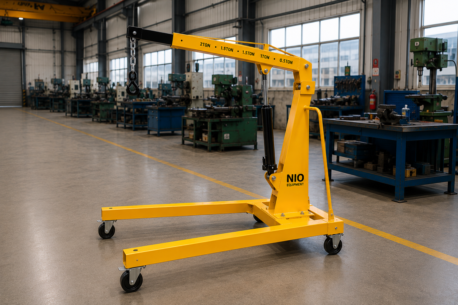
Nio Equipment Gantry Crane is a freestanding lifting system for moving machinery, fabricated structures, tooling, dies, and heavy industrial components. Its robust structural steel frame provides stable load support and clear-span working coverage without requiring a permanent overhead runway. Suitable for manufacturing, fabrication, warehousing, and maintenance operations, the crane can be customized for capacity, span, lifting height, girder arrangement, hoist selection, mobility, and site-specific operating conditions.
Specifications
| Capacity | 1 Ton to 20 Ton |
| Gantry Span | 3 m to 20 m |
| Lift Height | 3 m to 12 m |
| Gantry Height | Fixed or Adjustable, 3 m to 12 m |
| Girder Arrangement | Single Girder or Double Girder |
| Hoist Type | Chain Hoist or Wire Rope Hoist |
| Hoist Operation | Manual or Electric |
| Crane Travel | Fixed, Manual Push or Electric Motorized |
| Power Supply | 415V, 3-Phase, 50 Hz |
| Installation | Indoor or Outdoor, Fixed or Portable |
Key Features
- Heavy-duty fabricated steel gantry structure
- Wide clear-span lifting coverage
- Stable load-bearing frame geometry
- Smooth trolley movement across beam
- Supports precise hook positioning
- Accommodates concentrated industrial loads
- Accessible components simplify routine maintenance
Optional Configurations
- Load Capacity – Crane capacity can be engineered around the maximum lifted load, rigging weight, operating frequency, and required duty conditions.
- Span And Height – Beam span and gantry height can be selected to suit machinery widths, hook clearance, workspace dimensions, and building restrictions.
- Girder Arrangement – Single or double girder construction can be selected according to capacity, span, headroom, and required structural rigidity.
- Mobility Design – Fixed or portable gantry arrangements can be specified for dedicated lifting stations or movement between multiple workshop locations.
- Hoist Package – Manual or electric chain and wire rope hoists can be matched to lifting height, frequency, capacity, and positioning requirements.
- Environmental Finish – Paint systems and corrosion protection can be selected for indoor plants, outdoor yards, humid locations, or demanding industrial environments.
Safety Features
- Overload Protection
- Emergency Stop
- Hoist Limit Switches
- Fail-Safe Hoist Brake
- Travel End Stops
- Anti-Derailment Retainers
Certifications & Standards
Use Cases
Product Resources
What Is a Gantry Crane?
A Gantry Crane is a freestanding lifting system designed for heavy industrial material handling where permanent overhead cranes are impractical. It operates by spanning across an open workspace, providing flexible and clear-span lifting access for machinery, components, and fabricated structures. Commonly used in manufacturing, fabrication shops, and warehouses, it supports heavy load positioning and assembly tasks without requiring overhead runways.
Working Principle of Gantry Crane
The Gantry Crane operates using a hoist suspended from a girder supported by a rigid steel frame spanning the work area. The hoist moves horizontally along the girder, enabling load positioning. The structure is freestanding, eliminating the need for overhead support runways. Lifting is typically powered electrically or manually, converting the hoist motion into vertical load movement within industrial lifting capacity ranges.
Step-by-Step Operation
- Position the Gantry Crane beside the load to be lifted.
- Attach the hoist hook securely to the load or rigging.
- Lift the load vertically by operating the hoist.
- Travel the load along the beam using the trolley.
- Move the entire crane structure for lateral positioning if mobile.
- Lower the load to the desired location carefully.
- Detach the load and return the hoist to its starting position.
Key Components
Safety Features - Detailed
- Overload protection prevents lifting overloads
- Emergency stop halts all crane movement
- Hoist limit switches prevent over-travel
- Fail-safe hoist brake ensures safe holding
- Travel end stops prevent overrun
- Anti-derailment retainers keep trolley on beam
- Clear-span frame eliminates overhead obstructions
- Stable gantry frame reduces tipping risk
- Electrical protection integrated in power systems
- Visual safety signage recommended during operation
- Load rigging inspected before lifting
- Operator trained in safe use procedures
- Routine safety audits recommended
- Maintenance of safety devices mandatory
- Proper grounding to prevent electrical hazards
Selection Factors
- Load capacity requirements
- Beam span and height needed
- Type of hoist operation desired
- Fixed versus portable gantry design
- Required crane travel distance
- Operating frequency and duty cycle
- Workspace dimensions and clearance
- Environmental and site conditions
- Material handling process flow
- Safety feature requirements
- Installation space availability
- Structural support capacity
- Corrosion protection needs
- Maintenance access considerations
- Budget and total cost of ownership
Installation Requirements
- Level and reinforced foundation or floor
- Adequate clearance for gantry height and span
- Electrical 415V 3-phase power supply
- Provision for fixed or portable mounting
- Space for crane travel and maneuvering
- Access ramps or paths for portable units
- Structural floor support assessment
- Installation of travel end stops
- Operator training before commissioning
- Safety signage and workspace demarcation
- Commissioning checks and load testing
Maintenance Requirements
- Regular inspection of hoist and trolley
- Lubrication of moving parts and wheels
- Check structural welds for integrity
- Inspect and test overload protection devices
- Verify operation of limit switches
- Inspect emergency stop function
- Check for corrosion and repaint as needed
- Tighten fasteners and connections
- Examine electrical supply and controls
- Check travel wheels and rails for wear
- Inspect fail-safe hoist brake performance
- Monitor hoist wire rope or chain condition
- Clean components to prevent debris buildup
Advantages of Gantry Crane
- Freestanding installation requires no overhead runway
- Provides wide clear-span lifting coverage
- Customizable span and height options
- Supports heavy-duty load capacities up to 20 tons
- Versatile fixed or portable arrangements
- Smooth trolley and crane travel movement
- Enables precise load positioning and control
- Reduces infrastructure dependence
- Facilitates maintenance and tooling operations
- Simplifies heavy equipment relocation
- Improves workflow flexibility
- Optimizes factory floor space usage
- Adaptable girder arrangements per load demands
- Supports multiple hoist types and operations
- Accessible components ease routine maintenance
- Enhances worker safety with multiple protections
- Suitable for indoor and outdoor environments
Limitations of Gantry Crane
- Requires sufficient floor space for gantry footprint
- Limited crane travel compared to overhead cranes
- Not suitable for very high elevation lifts
- May need structural floor reinforcement
- Fixed gantry limits operational flexibility
- Portable models have weight and stability constraints
- Periodic maintenance needed for moving components
- Electrical supply dependency for motorized versions
- Environmental exposure affects corrosion resistance
- Hoist capacity limited by chain or wire rope ratings
- Requires clear floor paths for crane movement
Common Alternatives to Gantry Crane
Industry Applications
- Automotive Component Positioning
- Assembly Line Parts Transfer
- Tooling And Fixture Movement
- Production Support Material Handling
- Fixture Installation And Removal
- Automotive Subassembly Handling
- Supports organized material flow
- Reduces handling interruptions
- Improves production area coordination
- Lowers manual lifting risks
- Facilitates flexible load positioning
- Speeds tooling changeover processes
- Fabricated Part Movement
- Machined Component Transfer
- Tooling And Fixture Handling
- Work-in-Progress Positioning
- Structural Assembly Lifting
- Workshop Load Transfer
- Enhances material flow efficiency
- Reduces handling downtime
- Supports coordinated work areas
- Improves load positioning accuracy
- Facilitates heavy component movement
- Simplifies production material transfer
- Storage Level Material Transfer
- Mezzanine Load Movement
- Receiving Area Lifting
- Dispatch Area Handling
- Order Preparation Transfer
- Inventory Pallet Positioning
- Supports vertical inventory flow
- Reduces manual handling between levels
- Improves goods transfer safety
- Facilitates organized warehouse workflow
- Minimizes handling interruptions
- Enhances load placement accuracy
- Carton Movement Between Areas
- Packaged Goods Handling
- Packaging Material Transfer
- Production Support Supplies
- Storage To Dispatch Operations
- Crate Positioning For Loading
- Enables smooth material flow
- Supports operational level coordination
- Reduces handling disruptions
- Improves load transfer safety
- Enhances handling reliability
- Facilitates quick load repositioning
- Packaged Product Transfer
- Carton Movement Across Floors
- Container Handling For Storage
- Secondary Packaging Handling
- Production Material Lifting
- Operational Area Load Transfer
- Supports controlled material movement
- Improves organized operational handling
- Facilitates vertical product transfer
- Lowers manual handling demands
- Enhances load positioning precision
- Improves workflow continuity
- Receiving Area Load Transfer
- Storage Level Handling
- Dispatch Load Positioning
- Operational Floor Lifting
- Staging Area Material Movement
- Transport Vehicle Loading Support
- Maintains continuous goods movement
- Supports operational level coordination
- Reduces unnecessary manual handling
- Improves load transfer control
- Facilitates efficient staging operations
- Enhances workflow reliability
- Raw Material Handling
- Component Transfer Between Levels
- Work-in-Progress Movement
- Finished Goods Positioning
- Assembly Area Lifting
- Production Support Material Handling
- Supports organized material flow
- Reduces handling interruptions
- Improves storage and assembly transfer
- Facilitates safer load positioning
- Enhances operational floor efficiency
- Lowers downtime in handling
Applications
Industries Served
Customization Options
How Gantry Crane Compares to Alternatives
| Alternative | Key Difference |
|---|---|
| Floor Crane | Floor Cranes offer flexible mobility over flat surfaces but provide less overhead lifting clearance and span options compared to Gantry Cranes. |
| Jib Crane | Jib Cranes are limited to localized lifting with a pivot arm while Gantry Cranes provide wider span coverage across larger workspaces. |
| Mobile Floor Crane | Mobile Floor Cranes are highly portable for smaller loads but lack the heavy-duty capacity and overhead span of Gantry Cranes. |
| Wall Mounted Jib Crane | Wall Mounted Jib Cranes save floor space but restrict lifting coverage to a fixed radius unlike the free-standing Gantry Crane. |
| Hydraulic Floor Crane | Hydraulic Floor Cranes offer hydraulic power for lifting and better maneuverability in tight spots but are generally for smaller capacities than Gantry Cranes. |
| Overhead Bridge Crane | Overhead Bridge Cranes enable long-distance travel on fixed runway beams, suitable for high-elevation lifts, unlike the floor-based Gantry Crane. |
| Mobile Gantry Crane | Mobile Gantry Cranes combine gantry lifting with higher mobility but often involve higher cost and complexity compared to fixed Gantry Cranes. |
| Electric Hoist | Electric Hoists provide lifting assistance but require integration with a support structure, whereas Gantry Cranes include the full structural framework. |
✓ When to Choose Gantry Crane
- When handling heavy machinery and fabricated components requiring wide clear-span lifting without permanent overhead infrastructure.
- When installation space supports a freestanding crane with sufficient floor area and overhead clearance for gantry span and height.
- For indoor or outdoor industrial environments needing relocation or reconfiguration flexibility with fixed or portable gantry options.
- Where equipment maintenance, tooling changeovers, and assembly operations demand precise hook positioning and smooth trolley movement.
- When load capacities range from 1 to 20 tons with varying spans and lift heights adaptable to specific process or plant layout needs.
- If corrosion protection and environmental finishes are needed to ensure durability in humid or outdoor locations.
⚠ When Not to Choose Gantry Crane
- When available floor space is insufficient to accommodate the gantry footprint or structural reinforcement is impractical; consider jib or wall-mounted jib cranes.
- For very high elevation lifting requirements beyond 12 meters where overhead bridge cranes or tower cranes are more suitable.
- If operational flexibility demands extensive crane travel over long distances, overhead bridge cranes provide better runway-based coverage.
- Where personnel transportation or non-lifting industrial mobility is required; forklifts or material lift tables may be preferable.
- When load handling involves primarily palletized or forklift-compatible goods better served by forklifts or dock levelers.
- In environments with limited structural support capacity or restrictions preventing installation of freestanding heavy frames; consider floor cranes or hydraulic floor cranes.
Ideal Applications for Gantry Crane
Who Uses This Product?
Request a Custom Quote - What We Need to Know
- What is the maximum load capacity required for the gantry crane?
- What are the approximate dimensions of the largest load to be handled?
- What is the required gantry span and lift height for your application?
- Will the gantry crane be installed indoors or outdoors?
- What is the preferred hoist type and operation mode (manual or electric)?
- Is a fixed or portable gantry design preferred for your workspace?
- What is the expected operating frequency and duty cycle of crane use?
- Are there any space constraints for gantry height or footprint at the installation site?
- What type of material handling or loading/unloading method will be used with the crane?
- Do you require any specific environmental corrosion protection or finish?
Upgrade Options
Frequently Asked Questions
Why Choose NIO Equipment for Gantry Crane
Trusted by manufacturers, warehouses and industrial facilities across India for quality, reliability and after-sales excellence.
- ✓Application-specific crane engineering
- ✓In-house structural fabrication capability
- ✓Site layout integration expertise
- ✓Project engineering and installation support
- ✓Flexible hoist control integration
- ✓Responsive after-sales service support
About This Product
The Nio Equipment Gantry Crane is a freestanding industrial crane for lifting and positioning machinery, fabricated structures, dies, tooling, and heavy components. Unlike an overhead bridge crane, it does not depend on building-mounted runway beams, making it suitable where permanent overhead infrastructure is unavailable, undesirable, or impractical. It can support machine installation, plant maintenance, fabrication, assembly, warehouse handling, and equipment relocation workflows.
Freestanding Lifting Principle
The crane uses a hoist suspended from a trolley that travels along a single or double girder supported by rigid structural legs. The hoist raises or lowers the load, while trolley travel provides horizontal positioning across the span. Depending on the selected arrangement, the gantry structure may remain fixed, move by manual push, or use electric motorized travel for lateral positioning.
Industrial Operating Scope
Available configurations cover capacities from 1 ton to 20 tons, spans from 3 m to 20 m, and lift heights from 3 m to 12 m. Gantry height may be fixed or adjustable within the supported 3 m to 12 m range, subject to application and structural requirements. Indoor and outdoor installations can be configured with finishes appropriate to the operating environment.
Workflow Integration
A gantry crane creates a defined lifting zone above a work area without occupying that zone with a permanent overhead runway system. This arrangement supports vertical lifting, cross-beam trolley travel, and, where mobility is provided, movement of the complete crane between operating positions. It is particularly useful for tooling changes, maintenance bays, structural assembly stations, and workshop processes requiring controlled hook positioning.
Selection Context
The correct crane configuration depends on the maximum load including rigging, required span, hook clearance, duty conditions, movement pattern, floor capacity, and available workspace. A gantry crane requires sufficient floor area for its legs and a clear path where crane travel is intended. Applications involving loads above 20 tons, spans beyond 20 m, lift heights above 12 m, unusual load distribution, or restricted foundations require engineering review and may call for an alternative crane arrangement.
Applications
Machine Installation
During machine installation, the gantry crane can lift motors, gearboxes, machine modules, and other equipment from a staging position and place them over foundations or mounting points. Trolley movement allows the hook to be aligned with the installation location before the load is lowered. This controlled sequence supports accurate positioning where forklift access is constrained or unsuitable for suspended placement.
Die And Mold Handling
Tool rooms and production departments can use a gantry crane to move dies, molds, fixtures, and tooling between storage stands, maintenance areas, and machines. The clear-span beam enables the load to be raised above local obstructions and translated across the work zone. Hoist type, capacity, lift height, and control method should be selected around tooling mass, changeover frequency, and positioning demands.
Fabrication Shop Lifting
In fabrication shops, the crane can handle structural sections, welded assemblies, plates prepared with suitable lifting points, and work-in-progress components. It supports transfer between cutting, fitting, welding, inspection, and assembly positions within its operating coverage. A suitable span provides access across fabrication tables or assembly fixtures while maintaining space for safe rigging and load control.
Maintenance And Relocation
Plant maintenance teams can apply a gantry crane when removing or installing heavy components such as drives, motors, pumps, and gearbox assemblies. A portable configuration may allow one lifting system to serve multiple maintenance locations, provided travel surfaces and clearances are suitable. Fixed arrangements are better suited to recurring work at dedicated maintenance bays or machine service stations.
Assembly And Positioning
The crane supports industrial component assembly where parts must be suspended, aligned, and lowered into a controlled position. Smooth trolley movement across the beam helps place components over frames, fixtures, or subassemblies without relying on repeated floor-level repositioning. Chain or wire rope hoists may be selected according to capacity, lifting height, operating frequency, and required control.
Warehouse Load Handling
In warehouse receiving, storage, staging, and dispatch areas, a gantry crane can position pallets, packaged goods, inventory containers, and warehouse equipment when suitable lifting attachments and rigging are used. It may complement forklifts by serving a defined lifting zone where overhead access or vertical placement is needed. The load path must remain segregated from pedestrians, storage obstructions, and vehicle traffic.
Production Material Flow
Manufacturing facilities can use the crane for raw-material handling, work-in-progress transfer, production support, and finished-component positioning. The system is most effective where loads follow a repeatable route through a machine cell, assembly station, or workshop bay. Fixed, portable, manual-travel, or motorized-travel arrangements can be evaluated against process flow and required movement frequency.
Outdoor Yard Operations
A suitably configured industrial gantry crane may be installed in an outdoor yard for fabricated structure handling, equipment positioning, or maintenance activities. Environmental finish and corrosion protection should reflect humidity, exposure, and site contaminants. Outdoor applications also require assessment of the supporting surface, electrical protection, operating clearance, and site-specific environmental conditions.
Benefits
Reduced Infrastructure Dependence
Because the structure is supported by its own legs, the gantry crane does not require building-mounted overhead runway beams. This can make heavy lifting feasible in workshops, yards, leased facilities, or existing buildings where modifying the roof structure is impractical. Foundation capacity and floor loading still require assessment before installation.
Controlled Load Positioning
Vertical hoist movement and horizontal trolley travel provide two coordinated directions of load placement, with gantry travel adding another positioning direction where included. This helps operators align machinery, tooling, and fabricated parts with installation points or assembly fixtures. Controlled lifting can also reduce improvised manual repositioning around heavy loads.
Flexible Operating Coverage
Span, height, girder arrangement, hoist package, and mobility design can be selected around the work area rather than forcing the process into a fixed standard layout. Portable arrangements can serve changing workshop locations, while fixed cranes provide a stable lifting station for repeated tasks. This flexibility supports maintenance, production, and project-based handling requirements.
Improved Material Flow
A defined lifting path can reduce dependence on forklifts or floor-level handling for tasks requiring overhead suspension and precise placement. In fabrication and assembly workflows, components can move directly between adjacent work positions within the crane envelope. This can lower handling interruptions, shorten equipment changeover activities, and help keep production areas organized.
Maintainable Crane Layout
The fabricated frame, beam-mounted trolley, hoist, wheels, controls, and safety devices are accessible for routine inspection and servicing. Regular access to chains or wire ropes, brakes, limit switches, connections, and travel components supports preventive maintenance planning. Appropriate configuration and maintenance access can therefore contribute to reliable operation and lower avoidable downtime.
Safer Handling Practices
The crane replaces unsuitable manual lifting with a rated mechanical lifting system designed around the intended load and work area. Overload protection, emergency stop control, hoist limit switches, a fail-safe hoist brake, travel end stops, and anti-derailment retainers support controlled operation. These measures remain dependent on correct rigging, trained operators, inspections, and compliance with rated capacity.
Technical Highlights
Capacity And Geometry
Supported lifting capacities range from 1 ton to 20 tons, with gantry spans from 3 m to 20 m and lift heights from 3 m to 12 m. Gantry height can be fixed or adjustable within the specified 3 m to 12 m range. Final geometry must account for hook approach, load dimensions, rigging depth, machinery width, building clearance, and structural stability.
Structural Crane Frame
The load-bearing system comprises a heavy-duty fabricated steel frame, structural support legs, and a single or double girder beam. Stable frame geometry is used to carry concentrated industrial loads and maintain the intended lifting envelope. Girder selection depends on capacity, span, available headroom, and the rigidity required for the application.
Hoist And Trolley
The gantry crane may use a chain hoist or wire rope hoist with manual or electric operation. The hoist provides vertical lifting through a hook block and lifting hook, while the trolley moves the suspended load horizontally along the beam. Hoist selection should reflect load rating, lifting height, operating frequency, positioning needs, and anticipated duty conditions.
Crane Travel Options
Crane travel can be configured as fixed, manual push, or electric motorized. Fixed systems serve dedicated lifting zones, while portable or traveling systems provide movement between positions where the floor and access path permit. Travel wheels, end stops, and the operating surface must be evaluated together to maintain controlled movement and frame stability.
Electrical And Controls
Electric hoist and motorized-travel configurations use a 415V, 3-phase, 50 Hz power supply. Electrical components support hoist control, trolley or crane travel where powered, emergency stopping, and protective functions. Cable routing, grounding, isolation, control location, and protection from the installation environment form part of the project-specific electrical design.
Integrated Safety Systems
The safety arrangement includes overload protection, an emergency stop, hoist limit switches, a fail-safe hoist brake, travel end stops, and anti-derailment retainers. Overload protection limits operation beyond rated conditions, while the brake holds the suspended load when hoist motion stops. Limit and retention devices help prevent over-travel and unintended departure of moving assemblies from their intended path.
Environmental Configuration
The crane can be configured for indoor or outdoor installation and may be fixed or portable. Paint systems and corrosion protection can be selected for indoor plants, outdoor yards, humid locations, or demanding industrial environments. Environmental selection should consider moisture, airborne contaminants, cleaning practices, exposure, and maintenance access rather than finish appearance alone.
Industries Served
General Manufacturing
Manufacturing plants use gantry cranes to handle raw materials, production components, work-in-progress assemblies, and finished equipment within defined work zones. Typical workflows include transfer to machine tools, positioning at assembly fixtures, and movement between production and inspection stations. Span, lift height, and travel design can be matched to the cell layout and process sequence.
Automotive Manufacturing
Automotive operations may use the crane for engine components, gearbox assemblies, tooling fixtures, subassemblies, and production-support materials. Controlled overhead lifting assists tooling changeovers, fixture installation, component positioning, and maintenance around production equipment. A fixed lifting bay may serve repetitive tasks, while a portable arrangement may support several maintenance or tooling locations.
Metal Fabrication
Fabrication shops require movement of structural sections, fabricated parts, welded frames, machined components, and work-in-progress assemblies. A wide clear span can cover fitting tables or structural assembly areas while the trolley positions loads across the beam. Girder arrangement and hoist selection should reflect component weight, span, headroom, and handling frequency.
Engineering Workshops
Engineering workshops can apply gantry cranes to tooling, fixtures, motors, gearboxes, machined parts, and equipment maintenance tasks. The crane provides a practical lifting envelope around machines or service bays without requiring a building runway. Adjustable height or portable mobility may be considered where projects and workstation layouts change, subject to stability and floor conditions.
Warehousing And Logistics
Warehouse and logistics operations may use a gantry crane in receiving, staging, storage, dispatch, and vehicle-loading support areas. Suitable loads include palletized goods, packaged products, shipment containers, bulk boxes, and warehouse equipment when compatible lifting attachments are available. The crane is most appropriate for defined lifting zones rather than long-distance movement throughout an entire facility.
Tool And Die
Tool and die facilities handle dense, high-value dies, molds, fixtures, and tooling that require controlled lifting and accurate placement. A gantry crane can transfer these loads between storage supports, maintenance benches, and production machinery. Hoist control, hook clearance, load rating, and changeover frequency are important selection factors for this workflow.
Process And FMCG
Process, FMCG, and pharmaceutical facilities may use an appropriately configured crane for packaged products, crates, cartons, production supplies, containers, maintenance equipment, and secondary packaging materials. Applications commonly occur in receiving, storage, production-support, and dispatch areas where a suspended lift is required. Environmental finish, cleanliness expectations, access control, and compatibility with the facility's operating practices should be reviewed during specification.
Heavy Equipment Maintenance
Heavy equipment service areas need controlled removal and installation of machinery modules, drive components, assemblies, and structural parts. A gantry crane can establish a lifting bay over maintenance positions or provide portable coverage across several suitable work areas. Capacity must include rigging weight, and the floor must support both the crane and concentrated service loads.
Why Choose NIO Equipment
Application-Specific Engineering
Nio Equipment evaluates the crane around the load, rigging, operating frequency, workspace, hook clearance, and intended material path. This application-based approach helps determine whether a fixed, portable, manual-travel, or motorized-travel arrangement is appropriate. It also supports informed selection between chain and wire rope hoists and between single and double girder construction.
Configurable Crane Geometry
Nio Equipment can configure capacity, span, lift height, gantry height, girder arrangement, mobility design, hoist package, and environmental finish within the supported product scope. Adjustable gantry height, electric motorized travel, enhanced corrosion protection, and portable frame arrangements can be considered according to application requirements. Each configuration remains subject to structural, stability, site, and duty evaluation.
Manufacturing Integration Expertise
As an India-based manufacturer of material handling equipment and industrial lifting systems, Nio Equipment combines custom equipment design with in-house structural fabrication capability. The crane can therefore be developed around machine layouts, maintenance bays, fabrication stations, warehouse zones, and existing handling equipment. Site layout integration helps address crane footprint, travel paths, working clearances, and maintenance access before installation.
Project Qualification Support
Engineering consultation is available for unusual weight distribution, demanding duty conditions, specialized hoists, structural floor limitations, harsh environments, or requirements near the upper specification ranges. Nio Equipment can also assess applications exceeding the stated range to determine whether a revised design or alternative lifting solution is more appropriate. For an effective review, buyers should provide load details, rigging weight, span, height, duty, mobility, environment, and site constraints.
Installation And Lifecycle Support
Nio Equipment supports installation and commissioning planning, including site integration, operational checks, load testing coordination, and operator readiness. After-sales support can include maintenance guidance, spare-parts assistance, and technical support for the crane throughout its operating life. This continuity helps plant and maintenance teams manage the equipment as an engineered lifting asset rather than as an isolated hoist purchase.
Installation Guide
Site And Process Survey
Installation planning should begin with a survey of the load source, lifting point, destination, load dimensions, movement frequency, and surrounding operations. The survey should confirm required capacity, span, gantry height, lift height, hook clearance, and whether the crane will remain fixed or travel. Pedestrian routes, forklifts, machines, columns, services, doors, and stored materials must be considered in the load-path layout.
Floor And Foundation
A level, stable, and adequately reinforced floor or foundation is required to support the gantry footprint and operating loads. Structural assessment should consider wheel or leg reactions, lifted load, crane self-weight, dynamic effects, and the condition of the supporting surface. Sites with limited floor capacity, unusual load distribution, or restricted foundation depth require project-specific engineering evaluation.
Clearance And Travel
The installation area must provide adequate clearance for the selected span, height, hook travel, load envelope, and rigging. Mobile or motorized cranes also need a clear, level travel route with sufficient maneuvering space and suitable access between workstations. Travel end stops and workspace demarcation should be positioned to prevent movement into unsafe or obstructed areas.
Electrical Preparation
Electric configurations require access to a 415V, 3-phase, 50 Hz supply at a suitable connection point. Planning should include isolation, grounding, cable management, control access, and protection appropriate to indoor or outdoor conditions. Manual hoist configurations may not require hoist power, but any powered trolley or crane-travel function still requires the applicable electrical provisions.
Assembly And Access
Installation planning must allow safe delivery, unloading, assembly, and erection of the fabricated frame, girders, legs, trolley, and hoist. Space should remain available for inspection of welds, fasteners, wheels, brakes, controls, and safety devices after commissioning. Adjustable-height or portable designs require additional checks of locking arrangements, stability, access paths, and the approved setup procedure.
Commissioning And Testing
Commissioning should verify structural assembly, fastener condition, trolley alignment, hoist operation, travel movement, electrical functions, and correct operation of all safety devices. Travel end stops, overload protection, emergency stop controls, limit switches, brakes, and anti-derailment retainers should be checked before production use. Load testing, operator training, safety signage, and workspace demarcation should be completed in accordance with the equipment documentation and applicable site procedures.
Engineered Project Review
Additional consultation is appropriate for requirements near or beyond 20 tons capacity, 20 m span, or 12 m lift height, as well as for unusually distributed loads. Harsh outdoor exposure, extended duty cycles, multiple operating positions, specialized hoists, and integration with other material handling systems also require detailed review. The final arrangement should be based on site data rather than assumptions derived from nominal specification ranges.
Maintenance Guide
Pre-Use Condition Checks
Routine visual checks should identify damaged hooks, worn chains or wire ropes, loose components, fluid contamination from nearby equipment, corrosion, or obstructions in the travel path. Operators should confirm that the hoist, trolley, crane travel, brake, controls, and emergency stop respond normally before lifting. Unusual noise, vibration, skewing, or irregular movement should be reported and investigated.
Structure And Connections
Periodic inspection should cover the fabricated frame, support legs, girders, welds, fasteners, joints, and adjustable-height locking components where provided. Cracks, deformation, looseness, impact damage, or corrosion can affect alignment and load-bearing integrity. Repairs or structural modifications should only follow an authorized engineering assessment.
Hoist And Rigging Interface
The hoist mechanism, hook block, lifting hook, chain, or wire rope should be examined for wear, distortion, damaged strands, improper reeving, and lubrication condition. The fail-safe hoist brake should hold and release correctly without abnormal drift or shock. Maintenance frequency should reflect operating conditions, lifting frequency, load severity, and the recommendations in the equipment documentation.
Trolley And Travel Components
Trolley wheels, crane travel wheels, rails or running surfaces, bearings, and drive components require inspection for wear and free movement. Lubrication should be applied at designated points using the specified method, while debris that could interfere with wheel travel should be removed. Misalignment, uneven wheel wear, or repeated derailment indications require corrective investigation rather than continued operation.
Controls And Safety Devices
Electrical cables, control stations, connections, grounding, enclosures, and powered travel components should be checked for damage or deterioration. Overload protection, emergency stop controls, hoist limit switches, travel end stops, anti-derailment retainers, and brakes require periodic functional verification. Safety devices must not be bypassed to maintain production.
Corrosion And Records
Indoor and outdoor cranes should be cleaned sufficiently to expose structural and mechanical components for inspection. Damaged coatings and corrosion should be addressed using a finish compatible with the original environmental protection system. Inspection findings, maintenance work, safety-device tests, and component replacements should be recorded to support condition-based planning and trace recurring issues.
Safety Guide
Training And Authorization
Only trained and authorized personnel should operate the gantry crane or direct lifting activities. Training should cover controls, rated capacity, load rigging, hand or communication signals, emergency stopping, travel limitations, and pre-use inspection. The crane is intended for industrial load handling and must not be used to transport personnel.
Capacity And Rigging
The total suspended load, including rigging, lifting fixtures, and attachments, must remain within the rated crane and hoist capacity. Slings and lifting devices should be compatible with the load geometry and connected to approved lifting points. Side pulling, shock loading, dragging, or lifting an unsecured load can introduce forces outside the intended design condition.
Controlled Load Movement
The hook should be positioned over the load before lifting to minimize side loading and uncontrolled swing. Loads should be raised only enough to verify balance and rigging security before continuing the lift. Hoist, trolley, and gantry movements should be smooth, with personnel kept away from suspended loads and potential pinch or crush zones.
Travel Area Control
The operating area should be clearly marked and kept free of pedestrians, vehicles, stored goods, cables, and floor obstructions. Portable or motorized gantry movement requires particular attention to surface level, wheel paths, load stability, visibility, and stopping distance. A suspended load should not be traveled through an area that has not been assessed and cleared.
Protective Device Use
Overload protection, emergency stop controls, hoist limit switches, the fail-safe brake, travel end stops, and anti-derailment retainers support safe operation but do not replace correct operating practice. Their function should be verified through prescribed inspections and testing. Any defective or bypassed protective device is grounds to remove the crane from service until the condition is corrected.
Isolation And Maintenance
Before maintenance, adjustment, or inspection within a hazardous area, energy sources should be isolated according to the site's lockout and tagout procedure. Suspended loads must be removed or safely supported, and moving assemblies should be secured against unintended movement. Unauthorized changes to the frame, hoist, controls, wheels, height adjustment system, or safety devices can invalidate the engineered operating condition.
Application Risk Review
Project-specific safety review is required for unusual load distribution, harsh outdoor exposure, constrained floor capacity, specialized hoists, extended duty, or integration with other equipment. The review should address rigging methods, operator visibility, access control, environmental effects, communication, and emergency response. Requirements outside the validated capacity, span, or lift ranges should be referred for engineering evaluation before equipment selection.